A coupling transmits power from a driver to a driven piece of equipment. The driver can be anything from an electric motor to a steam turbine, and the driven equipment can be a gearbox, fan or pump. While the coupling is often viewed as the weak link in the pump assembly, replacing a coupling element is still much easier than replacing a sheared shaft.
For the purposes of this article, the driver will be an alternating current (AC) electric motor, and elastomeric couplings will be the focus. Typically, these couplings consist of three to six components, excluding fastener hardware. They have two hubs with bores to match the drive shaft and driver shaft and an elastomeric element between them. Some couplings, especially spacer types, have more components. A spacer coupling assembly, for example, can have two shaft hubs, two flanges and one elastomeric element. The assembly bolts together in such a way that the two flanges and element drop out of the center section.
Based on the calculation for horsepower (HP) indicated in Equation 1, the proper sizing of couplings is highly dependent on HP, torque and shaft speed. In addition to these variables, other elements such as service factor and misalignment capabilities can affect coupling operation and application. For this reason, many users rely only on the manufacture's methods for proper sizing. Reading a few coupling manuals will indicate that a vast selection of couplings can meet a user's power criteria. Still, selecting the best coupling for the job depends on the environment and the operators just as much as the mathematics behind the sizing. When selecting a coupling for a pump application, end users should consider the following factors.
 Where
HP = horsepower
T = torque (inch-pounds)
n = shaft speed
Service Factor
Service factor is an application- and coupling-dependent multiplier that should be factored into sizing data. It is a buffer between the torque capacity used to size a coupling and what happens in the real world. For example, if a pump requires 500 inch-pounds (in-lb) of torque and the coupling manual recommends a 1.2 service factor, the coupling would be sized for 600 in-lb (500 in-lb x 1.2 = 600 in-lb). This is to help compensate for application details such as shock loads, type of driver and type of driven equipment. Each type of equipment has its own load characteristics and can generally be found in the sizing section of a coupling manual; if not, consult the manufacturer. Always use the service factor recommended for the particular coupling to be used, and resist the urge to oversize the coupling. The coupling is meant to be the weak link.Fail Safe
A fail-safe coupling will transmit power even after the element fails, because part of both hubs operates in the same plane. A jaw coupling is an example of a fail-safe coupling. Alternatively, couplings that are not fail-safe are also available. When the element fails, these couplings will no longer transmit power, because no part of the hubs operates in the same plane.Load Characteristics
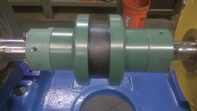
Users should always know the load characteristics for their pumps. Are uniform or non-uniform loads expected? Is this a variable-torque (centrifugal pump) or constant-torque (positive displacement) application? Starting torque is particularly important. Progressing cavity pump applications are a prime example of an application where starting torque is much greater than the running torque. This possibility must be taken into consideration during coupling sizing. The number of starts and stops per hour also plays a role in selection. Image 1. Spacer couplings are engineered to have a drop-out center section to allow for easy removal of the pump rotating assembly without having to unbolt the motor. (Images and graphics courtesy of Fischer Process Industries)
Back Pull-Out Design
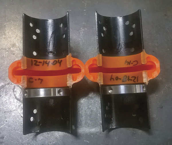
When specifying a coupling for a pump that uses a back pull-out design, a spacer coupling is an ideal choice. Spacer couplings are prominent in the pump industry and are available in a wide variety of designs. They are engineered to have a drop-out center section to allow for easy removal of the pump rotating assembly without having to unbolt the motor (see Image 1). The distance between shaft ends (DBSE) must be large enough to allow the rotating assembly to be removed without having to unbolt the motor. A coupling with a DBSE that is too small can lead to a flawed buildup and require the maintenance personnel working on the pump to move the motor in order to remove the rotating assembly, which defeats the purpose of a back pull-out design. Image 2. Radially split elements can typically be replaced with less effort and without the need to unbolt flanges from hubs.
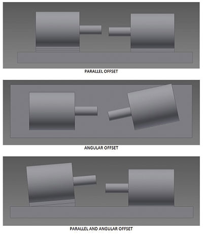
 Figure 1. Shaft misalignment includes parallel offset, angular offset and a mixture of the two.
