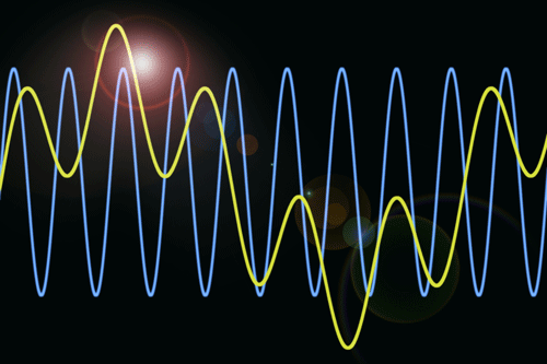
An ordinary variable frequency drive (VFD) generates harmonics at both its input and its output. On the motor (output) side, the VFD emulates a sine wave with a pulse width modulated (PWM) signal. The difference between the two signals is shown in Image 1. The PWM signal is somewhere between a square wave and a pure sinusoid. The squared-off nature of the PWM signal results from the limited switching frequency of the integrated gate bipolar transistors (IGBT), commonly used in ordinary VFDs. Harmonics are an inevitable and unfortunate by-product of a PWM signal.


IMAGE 1: Sine wave vs. PWM signal (Images courtesy of SmartD)
The situation is similar on the grid (input) side of the VFD. The diode bridge architecture used in ordinary VFDs draws current nonlinearly at the peak of the voltage waveform. The resulting current waveform (Image 2) is heavy in harmonic content, which is propagated back onto the electrical distribution network. It is not uncommon for an ordinary 6-pulse VFD to generate total harmonic current distortion (THDi) in the range of 80% on both the grid side and the motor side of the VFD.
.jpg)
IMAGE 2: Input voltage and current waveform
By definition, harmonics occur at integer multiples of the fundamental frequency. For example, a 60 hertz (Hz) system will experience harmonics at second—120 Hz, third—180 Hz, fourth—240 Hz, fifth—300 Hz, etc. Each harmonic can be further categorized as positive sequence, negative sequence and zero sequence components. Positive sequence harmonics (fourth, seventh, tenth, thirteenth, nineteenth, etc.) have the same rotational vector as the fundamental frequency. As the name implies, negative sequence harmonics (second, fifth, eighth, eleventh, fourteenth, etc.) rotate in the opposite direction as the fundamental. Zero sequence components (third, sixth, ninth, twelfth, fifteenth, etc.) have no rotational vector.
Impact of Harmonics
The fact that the motor output of an ordinary VFD contains harmonics means that the total root mean square (RMS) current in the motor is significantly higher than the fundamental current. This excess current manifests as increased copper and core (iron) losses, which in turn increase the heat within the motor itself. In the short term, excess heat can cause thermal nuisance-trips, directly hampering operations. Over the longer term, the excess heat will degrade the motor insulation, leading to early failure.
Concerns about harmonics are not limited to excess RMS current. The high rate of change of voltage (dv/dt) generated by harmonic-induced eddy currents can cause arcing between both the individual motor windings and between the bearings and bearing raceway. The former degrades the motor insulation, while the latter causes bearing pitting and lubricant breakdown. The relative magnitude of individual harmonics can have an impact on motor performance and longevity. As noted above, negative sequence harmonics operate in the opposite direction of the fundamental, creating the potential for heating of the rotor through large eddy currents.
Additionally, the interaction between adjacent positive and negative harmonic currents can create pulsating torque and mechanical oscillation, reducing operational efficiency. Similar to motors, the presence of harmonics in an electrical distribution system means that conductors must be oversized within the facility, requiring additional capital expense and limiting options for subsequent expansion and reconfiguration. Other equipment attached to the electrical network may be subject to excessive heating, premature wear and early failure.
The specifics will depend on the type of equipment. Some examples include excessive heating within transformers, visible flicker on lighting loads or damage to sensitive loads. Electrical utilities are keenly aware of how excess harmonics negatively impact their distribution grids. Most require that users comply with the limits specified under Institute of
Electrical and Electronics Engineers (IEEE) 519, which requires that THDi must not exceed 5% at the point of common coupling. Those who fail to comply are subject to financial penalties.
Harmonics Mitigation
Given the many problems associated with high THDi, manufacturers have developed ways to mitigate their impact on both motors and the electrical network. However, all these mitigations come at the cost of increased capital investment, reduced system efficiency, larger physical footprint and ongoing maintenance cost.
For example, a sinusoidal filter installed between a VFD and a motor will reduce (but not eliminate) harmonics, helping to mitigate the type of damage discussed above. Similarly, installing a line reactor or a passive filter between a VFD and the electrical distribution network will reduce the harmonic content released onto the grid.
Unfortunately, line reactors only reduce the THDi from 80% to 40%, which is not enough to meet the 5% requirement specified under IEEE 519. A passive harmonic filter can meet the IEEE 519 limit, provided it is properly tuned and well maintained, but again at the cost of space, time, system efficiency and ongoing maintenance.
Eliminate, Do Not Mitigate
In general, it is better to eliminate a problem at the source rather than attempt to mitigate it afterward. A VFD with a low THDi on both input and output eliminates the need for the costly and complex mitigations necessitated by ordinary drives.
Recently, some drive manufacturers have begun to take advantage of the new generation of wide-bandgap (WBG) semiconductor technology, namely silicon carbide (SiC) and gallium nitride (GaN), to address this challenge. WBG metal-oxide semiconductor field-effect transistors (MOSFETs) facilitate a dramatic increase in switching rate, beyond that of ordinary IGBTs. Deployed in active front end (AFE) architecture, the THDi on this type of drive inputs meets the 5% limit under IEEE 519.
Similarly, the true sine wave output on the motor side reduces motor wear. Additional benefits of WBG-based drives include improved drive and system efficiency, smaller installation size, longer motor life with a lower cost general purpose motor, no filter maintenance, ease of scaling, lower overall installation cost and reduced system complexity.

