Induction motors come in a wide range of sizes and styles, with some machine styles dictated by limited design choices and others resulting from negotiations between user and manufacturer. Generally, the guiding factors for how a motor is constructed are based on the protection needed (such as the enclosure), the rating of the machine (horsepower [hp]/revolutions per minute [rpm]/voltage), and how the motor interfaces with driven equipment (vertically or horizontally, and shaft extension arrangements). Additionally, virtually all motors have the same basic parts including an enclosure, frame, wound stator, rotor assembly with shaft, bearing(s) and associated bracket(s), as well as various termination points and accessories.
Enclosures
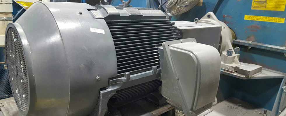
Along with general size and mounting, an enclosure has an impact on a motor’s appearance, construction and often overall acoustic performance. For small motors, enclosure choices are generally limited to those that are integral to the motor’s frame and bearing brackets and are usually totally enclosed fan-cooled (TEFC), totally enclosed nonventilated (TENV), or open drip proof (ODP). Medium motors have the same enclosures and styles available to them as small motors but might additionally be available with enclosures that require separate assemblies including external air boxes or hoods (also called top hats or air cabinets) that create enclosures including weather protected (WPI and WPII) and sometimes water jacket cooling. For large motors, excluding TEFC and ODP (which are generally rarer for them), enclosure options include those previously mentioned and typically also require separate assemblies to mount to the housing and/or bearing brackets. Additional enclosure options for large motors include totally enclosed air to air-cooled (TEAAC/CACA), totally enclosed water to air cooled (TEWAC), totally enclosed pipe-ventilated (TEPV), and a few other specialty arrangements. Motors requiring variable speed operation can use forced ventilation assemblies (e.g., external blowers or independently driven fans) that adapt to the motor’s enclosure to supply ventilating air when needed. Internal baffles, which might direct airflow inside of the motor, protect against foreign material intrusion or both, are also integral to almost all motor enclosures. In addition to enclosure features meant to provide environmental protection or aid in cooling the motor, there are typically various covers on medium and large machines meant to provide access to items such as space heaters and air gap dimensional check provisions.
Frames
Generally, motor frames (housings) tie together the motor’s various assemblies and mount the motor to its foundation with feet (for horizontal machines) or support the weight of the upper bearing bracket (for vertical machines). For small motors, frames are cast iron, aluminum or rolled steel. Grey iron is most common for general purpose applications and ductile iron being available for applications with frequent shock loading. According to size and enclosure, medium motors might be available in cast iron or fabricated steel arrangements. Large motor frames are almost exclusively fabricated from steel and require stress relieving prior to final machining. A final function of motor frames is holding the wound stator in place, which can be accomplished through methods including a shrink fit, close fits that are then welded or dowelled, or for some large machines, having the laminated stator core built integral with the fabricated frame.
Wound Stators
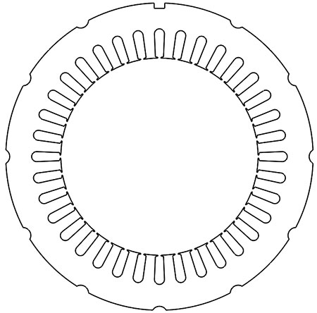
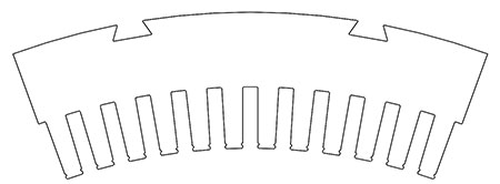
Wound stators contain the laminated electrical steel core that holds a motor’s windings and are rarely visible from the outside of a machine. In addition to having varying styles of holding together the stator laminations under pressure, wound stators are available in random wound (for low voltage) and form wound (for medium and high voltage) arrangements. Small motors are almost universally random wound and generally have their lamination stacks held together via welding, cleating or in rare cases specialty adhesives. Medium motors can be random or form wound and have their stacks held together via welding, cleating or sometimes with tie-bar construction, which involves steel rods welded to press plates on either end of the stator core. Large motors are form wound with lamination stacks that use tie-bar construction, dovetail interfaces to frames, through-rod construction, and can additionally have their lamination circles made of full “cookie” blanks or segmented laminations according to diameter.

Rotors
Rotor construction varies according to machine size, application, mounting orientation and manufacturer/user preference. All rotors will consist of conductors (squirrel cage or wound rotor type) housed in a laminated core and mounted on a shaft or other mechanism to transfer torque between the motor and load. Squirrel cage rotors are typically cast aluminum for small and medium machines, with specialty applications sometimes requiring cast or fabricated copper alloy bars and end (shorting) rings. Large machines almost universally use a fabricated copper alloy squirrel cage, with some manufacturers offering the option for fabricated aluminum cages. Rotor slot and bar shapes come in a variety of shapes, with small motors typically having a specialty shape to optimize starting and running performance, and large motors typically using a rectangular rotor bar, sometimes modified for improved performance. The end (shorting) ring assemblies are typically cast against the ends of the rotor core body on small and medium motors and are usually brazed at the ends of or underneath the rotor bars on large machines.
Shafts serve several functions for a motor including mounting the rotor core, providing bearing journals, moving shaft fans to induce air flow and transferring torque to the driven equipment. Generally motor shafts are solid with cylindrical, keyed drive fits but also come in other versions including hollow (for pumps), flanged (for large reciprocating compressors), splined, and sometimes tapered keyless drive fits for high-speed applications. According to size and application, shafts are machined from a single piece of stock or from forged rounds and might additionally have carbon steel spider bars that span large diameter differences between the shaft outer diameter and rotor lamination inner diameter on medium and large machines. Rotors will always have some provision(s) for balancing of the assembly, which can be on cooling fans, spider bars or end rings.

Bearings & Mounting
To support the weight and facilitate rotation of rotors, motors require some form of bearing(s) between their rotor assemblies and stationary components. According to machine size, speed and application, bearings are available in antifriction (rolling element), sleeve (typically babbit-lined), or tilting pad bearings (either for large vertical or high-speed horizontal). Generally small and medium motors (vertical and horizontal) use antifriction bearings with grease lubrication. Large machines may use either grease-lubricated antifriction, but more commonly use oil-lubricated sleeve bearings with large vertical machines typically having oil-lubricated upper thrust bearings and either an antifriction or sleeve lower guide bearing. Although rare, oil lubrication is also available for antifriction bearing applications but generally requires more upkeep in operation than grease lubrication.
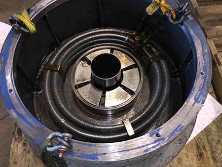
Bearings are able to transfer the rotor’s weight to the motor frame through the use or bearing brackets (also known as end bells, end shields or bearing housings) and have their chamber enclosed through some type of bearing cap (sometimes known as a bearing retainer). Most often, bearing brackets are made of cast iron, but on large or specialty machines might be either full round or half round fabricated steel assemblies. In the case of vertical motors, lower bearing brackets serve the purpose of aligning and connecting to the motor’s base, while upper brackets must house the thrust bearing assembly. In large vertical machines, there are often cooling coils in the upper bracket’s oil bath to maintain a constant oil temperature in addition to stand pipes, which prevent oil from leaking into the motor. Finally, according to enclosure, brackets might have ventilating passages through them, be completely closed or have some cooling fins for the dissipation of heat.

Terminal Boxes & Accessories
In addition to the structural assemblies of a motor, there are also terminal boxes that provide termination locations for power and accessory leads as well as various accessories typically dictated by the end user. Motors will always have leads from their wound stators that exit their frames and to ensure safety and clean interfaces, these leads are almost always housed in a dedicated main terminal box sized per electrical code and for accommodating any required accessories (current transformers, potential transformers, lightning arrestors, etc.). These boxes can be made from cast iron or fabricated steel and will mount to the motor’s frame. Additionally, there are often auxiliary terminal boxes that house terminations for items including resistance temperature detectors, vibration probes or space heaters. There are countless options for accessories to motors including bearing lubrication provisions, temperature sensors, vibration probes, space heaters and water leak detectors. All of these can be a point of specification between the user and manufacturer.
Though all motors consist of the same core group of assemblies to convert electricity into mechanical power, the specific construction of these machines can vary. From enclosures protecting and cooling a motor to rotor construction styles dictating how a machine can be balanced, motor construction differences play a key role in purchasing, using, maintaining and servicing these machines.

