
I hope that my last column (Pumps & Systems, September 2014) provided a clearer definition of power factor and how it can be calculated. Power factor can also be explained using a vector triangle, but comparing the voltage and current wave forms is more intuitive and can lead to a clearer understanding of what is actually going on. In short, power factor is the percentage of the total current in the circuit that does work. From a power perspective, it is the percentage of apparent power in kVA that actually performs work. It is also the ratio of the load power measured in kilowatts (kW) to the apparent power measured in kilovolt-amps (kVA). Why is power factor important? After all, the current required to initiate a magnetic field in the stator is returned to the electrical grid when that field decays. However, power factor is important for several reasons. Even though the current is returned, the utility still has to supply it during each alternating-current (AC) cycle. Because it is not recorded by the kilowatt-hour meter, the utility does not get paid. Also, it is not available for sale to other customers because it must be available to meet the power factor requirement of the motor. Another reason is the increased wire and transformer size that is required to provide the additional current. These factors affect both the utility and the customer.
Real-World Example
A 30-horsepower (HP), 460-volt (V) motor has a nameplate efficiency of 94 percent and a power factor of 85 (0.85). The nameplate also shows a full load amperage (FLA) of 35 amps (A). Based on the power factor, the current used to drive the motor load is 29.75 A (35 A multiplied by 0.85). The additional 5.25 A are used to initiate the magnetic field in the stator and are returned to the electrical grid when the field collapses. A power factor of 0.85 is probably not a big deal when a single 30-HP motor is operating. The power company likely would not notice the extra 5.25 A. If, however, this motor is in a plant and operating with many other motors, power factor becomes important. Suppose a plant operates 20 30-HP motors from a central motor control center (MCC). The load portion of the current increases to 595 A, and the magnetic portion increases to 105 A (700 A total). Chances are that the power company would get involved because the magnetizing current is now the equivalent of three additional 30-HP motors. Also, the wiring providing power to the MCC must be sized for 700 A. As HP and the number of motors increase, magnetizing current becomes a costly item for both the utility and the plant. If the power factor for these motors could be increased to 95 (0.95), the total current used by the MCC would be reduced to 626 A. At first glance, a reduction of 74 A may not seem significant. However, in a 460-volt, three-phase circuit, a 74-A reduction equates to about 59 kW. That is the equivalent of removing about 74 HP from the utility’s grid that would be available for sale to other customers. It would also increase the plant’s transformer capacity and decrease the wire size for certain circuits. For example, conductor size typically doubles when the power factor is reduced from 100 to 70. In addition, plant voltage will often increase by 1 to 2 percent.Capacitors
Motors can be designed for high power factor, but those design changes usually result in reduced efficiency. Today, most motors are designed for high efficiency because lower power factor can be corrected on-site with the help of a simple device—the capacitor. The capacitor is also a reactive device, but it behaves differently than the reactance caused by motors and other inductive loads. Fortunately, this behavior allows it to correct the problems associated with low power factor. A capacitor can be compared to a battery because both store and release a charge. A major difference is that the capacitor can store and discharge all its stored energy in a fraction of a second, but a battery will take far longer. A fitting example of a battery and capacitor working together is the electronic flash on a camera or smartphone. A battery charges the capacitor in several seconds, and the capacitor instantly dumps the full charge, causing the bulb to flash. Figure 1 shows one complete AC cycle for a circuit that contains a motor and capacitor. The blue curve represents voltage. The red curve is the motor magnetizing current, and the green curve is the capacitive current. The load current is not included to help keep Figure 1 visually simple.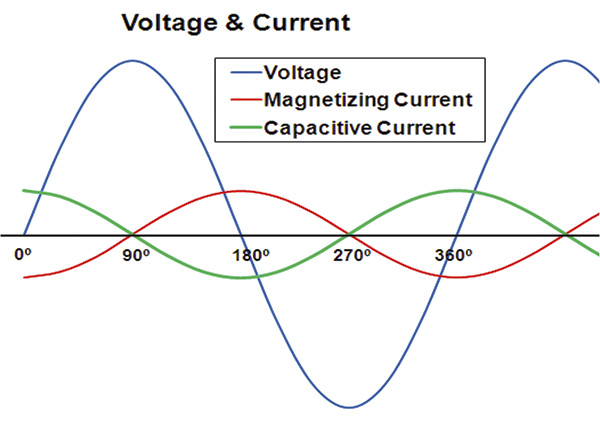 Figure 1. A complete AC cycle for a circuit with a motor and capacitor (Graphic courtesy of the author)
