06/27/2014
Piping plans for mechanical seals are used to improve the environmental conditions around a seal, extend its capabilities and allow operators to monitor seal performance. American Petroleum Institute (API) 682 contains the most widely referenced specifications for mechanical seal piping plans. This standard includes existing piping plans used in the field and introduces new piping plans that follow advancements in technology and respond to improvements required by the industry.
Single-Seal Design
Single seals (API 682 Arrangement 1) are the most commonly used seals in most industries. Reliable performance and simple setup make these a good choice for many applications. One challenge with this design, however, is detecting seal performance degradation and minimizing leakage in the case of a failure. This becomes even more challenging if the pump is located in a remote area or at an unmanned facility. In many cases, these applications use API Piping Plan 65, which captures leakage from the pump and detects it in a remote detection vessel. While this is effective, it is often only sensitive to large leak rates. API 682 4th Edition introduced two new options to improve monitoring capability: Plan 66A and Plan 66B. On a conventional single seal, leakage that migrates past the seal faces enters the drain cavity and exits the gland at the drain port. The leakage often falls into the bearing bracket and is piped to a drain or collection system. If significant seal failure occurs, liquid can fill the drain cavity and spray past the throttle bushing and the drain port. This can be unacceptable from both a personnel exposure and an environmental perspective.Plan 66A
API Plan 66A is a piping plan designed for earlier detection of seal leakage and for minimizing leakage from the seal gland. The plan is similar to a conventional, single-seal design with the addition of a close clearance bushing installed between the stationary seal face and the drain cavity (see Figure 1).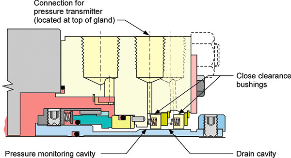 Figure 1. API Piping Plan 66A overview
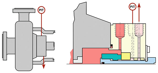 Figure 2. API Piping Plan 66A schematic
Plan 66B
An alternative version of this piping plan, Plan 66B, is also included in API 682. This version is similar to a standard, single-seal design with the addition of an orifice plug in the drain port (see Figure 3). An orifice plug is a solid metal plug drilled to prevent process fluid from leaving the seal gland. According to the standard, the orifice size should be 0.062 inch (1.5 millimeters) for clean, low-viscosity fluids and 0.125 inch (3 millimeters) for dirty or high-viscosity fluids. Because this piping plan only requires the addition of a drain plug and pressure monitoring port, it requires no more space than a conventional seal and may allow end users to retrofit existing seals in the field.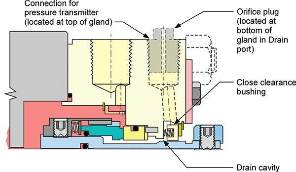 Figure 3. API Piping Plan 66B overview
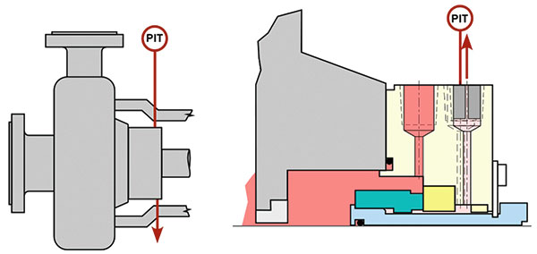 Figure 4. API Piping Plan 66B schematic
We invite your suggestions for article topics as well as questions on sealing issues so we can better respond to the needs of the industry. Please direct your suggestions and questions to
sealingsensequestions@fluidsealing.com.