Wastewater collection systems are difficult to monitor, control and operate, but solutions are available.
Endress+Hauser

Ideally, the flow of wastewater from collection points at residences, offices and commercial establishments to wastewater treatment plants would be completely gravity-powered. This is rarely possible because of economic or physical limitations. The most common challenge is flat terrain, which cannot easily be graded to promote wastewater flows. As a result, lift stations must be employed to move wastewater to a higher elevation and eventually to a wastewater treatment plant (see Image 1). A typical wastewater collection system in a county or large city will have hundreds of lift stations, with smaller lift stations feeding into larger master lift stations. These, in turn, feed wastewater to the treatment plant.
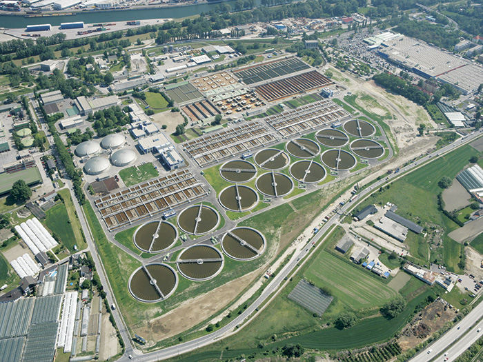
wastewater treatment plantImage 1. This wastewater treatment plant receives wastewater from a network of lift stations, each of which must be controlled and monitored to assure correct operation. (Images and graphics courtesy of Endress+Hauser.
Pumps are installed at each lift station to draw wastewater from the lift station’s wet well, the wastewater receiving point, and transfer it to a higher elevation. Typically, each lift station is equipped with two or more pumps, with operation alternating between the pumps to increase reliability. In high-flow situations such as heavy rain, multiple pumps can be operated simultaneously, which increases flow from the wet well. Pumps can be mounted on the floor of a wet well or in a dry pit adjacent to the well. Monitoring and control of these lift stations—especially considering the process variables in these harsh environments—presents many challenges.

Lift Stations Controls

As shown in Figure 1, pumps are typically installed below the lowest point of the incoming wastewater feed pipe. Smaller lift stations might have a single 4-inch feed pipe, while larger stations can have multiple feed pipes, each up to 36 inches in diameter.
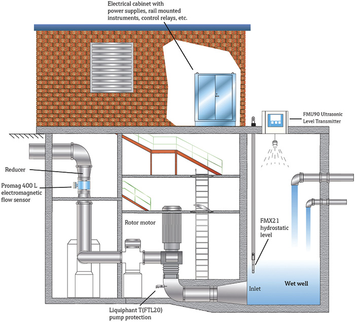
typical lift stationFigure 1. This diagram depicts a typical lift station. Key components include the wet well, the pumps, the instrumentation and the automation system used for the station’s control and monitoring.
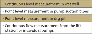
When the wastewater level reaches a critical point, a control system starts one or more pumps to prevent wastewater from overflowing the well, which could contaminate groundwater or local waterways. These spills could negatively impact residents and require costly cleanup. Wastewater often contains grease and solids, and foam is frequently produced because of turbulence in the lift station. These solids and foam can impair standard measuring techniques and instruments, causing high failure rates and requiring frequent maintenance. Conditions inside lift stations are not instrument-friendly because of high moisture levels, condensation and sewer gas. An instrument in the pump station—either a transmitter or a switch—measures each of the parameters listed in Table 1. A transmitter continuously measures a parameter across a wide range—for example, 0 to 15 feet of wastewater level in a wet well. The transmitter then sends a signal proportional to the measured value to the control system. A switch simply measures an on-off condition such as whether a certain level has been reached by wastewater in a lift station. The switch then sends an on-off signal to the control system.
TableTable 1. Parameters measured in lift stations
The control system in a lift station is typically a programmable logic controller (PLC), which uses inputs from the instruments along with its internal programming to control operation. The PLC often is integrated with a central supervisory control and data acquisition (SCADA) system at the wastewater plant to provide enterprise-wide connectivity and visibility. For smaller and/or remote lift stations not monitored by a PLC/SCADA system, paperless data recorders often are installed. These recorders accept lift station signals from instruments, provide alternating pump control, and record and store relevant data.

Level Measurements

Wet well level is the most critical measurement parameter in a lift station because level information is used to start and stop the pumps. Older lift stations often use a simple float switch to start and stop a single pump. But this technology is often insufficient because grease buildup and accumulation of debris can cause the switches to stick. Even when working correctly, a float switch only provides a single-point measurement, as opposed to a transmitter that gives a more informative continuous indication of wet well level. Bubbler level transmitters are an older technology used for this continuous level measurement, but they require a constant air supply and use tubes that can become easily clogged. Instead, modern lift stations use float switches for emergency backup and employ newer continuous level measurement technologies—namely hydrostatic and ultrasonic instruments. Hydrostatic level transmitters can be safely submersed in wet wells and effectively avoid float switch and bubbler issues. Hydrostatic level transmitters measure water pressure within the wet well and infer level from changes in the head pressure. Because it can resist abrasion, scratching and denting, a ceramic pressure-measurement cell is typically used with a hydrostatic level transmitter. Ceramic cells are sensitive enough to perform properly in the harsh environment of a wet well and provide accurate measurements even with the buildup that can occur on the cell. Ultrasonic level measurement instruments are non-contact devices that measure level by sending an ultrasonic signal from the top of the wet well to the surface of the wastewater.
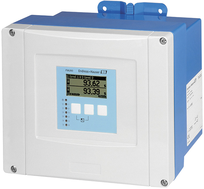
ultrasonic level transmitterImage 2. This ultrasonic level transmitter can be used to provide reliable and accurate measurements of wet well level in lift stations.
A transducer mounted inside the lift station at the top of the wet well sends and receives the ultrasonic signal. The signal bounces back from the wastewater, and the instrument uses this time-of-flight information to infer level. Condensation inside the lift station that accumulates on the transducer’s face can be a potential problem. A self-cleaning sensor will detect the buildup of condensate, automatically increase the amplitude of the excitation signal and knock the condensation off the face of the transducer without interrupting the measurement signal. Because wet well levels are a critical measurement, master and other larger lift stations often use both technologies simultaneously to provide redundant wet well level measurement.

Other Measurements

Pumps mounted on the wet well floor are submersible and typically do not require inflow or outflow measurement, but they pose other issues related to reliability and maintenance. Because of these challenges, pumps often are mounted outside the wet well, and adding points of measurement can help improve their operation. Centrifugal pumps are commonly used in lift station applications and can be damaged if they run dry. This issue can be avoided by installing a point level switch in the pump suction pipe. Leak detection in dry pit designs is a common concern, and a level-limit probe is an ideal solution because it provides millimeter accuracy for detection of water in the dry pit. The contacting liquid-limit probe is adjustable, and the measurement rods can be shortened in the field. Multipoint detection is available to indicate different levels. Another commonly measured parameter is output flow from the pumps or from the entire lift station. Many flow-measurement technologies are susceptible to errors created by the harsh lift station environment. High levels of solids and grease create inaccuracies or maintenance problems for insertion-style flow meters. Electromagnetic flow meters, or mag meters, are typically used in lift station applications because they overcome these and other issues. Mag meters have no moving parts and introduce little or no pressure loss. Modern designs employ a high-impedance amplifier to eliminate problems often associated with electrode fouling and to run self-diagnostics on a continuous basis to check the meter’s overall health. For large pumps used in master lift stations, the mag meter’s signal is often used as the process variable in a PLC or proportional–integral–derivative (PID) controller. The controller compares the actual flow to the desired flow set point and adjusts the pump speed using a variable frequency drive. This saves a considerable amount of energy compared with running the pump at full speed and allows for greater flow control within the wastewater collection system.

Smart vs. Analog Instruments

Level transmitters, pump inflow switches and pump outflow transmitters are either basic or smart. Basic instruments simply output a value corresponding to the parameter sensed, an on-off signal in the case of a switch, or a 4-20 milliamp signal in the case of a transmitter. Smart instruments have a high-speed, two-way digital communications link to the control system. For switches, diagnostic information can be sent to the control system in addition to on-off information to show if the switch is working properly. Smart transmitters communicate not only the main process variable but also other variables and information to the control system. They can receive calibration information. Data sent to the control system includes diagnostic information and other process variables in addition to the primary measured variable, such as temperature for a level or flow transmitter. Lift station operation is relatively simple and well understood, but problems often arise because of errors in the measurement of wet well level, pump inflow, pump outflow and other parameters. Installing the right instruments for each of these measurement points ensures reliable lift station operation and keeps wastewater flowing from collection points to the treatment plants without overflows or spills.