Follow these tips to help keep gremlins away from your system.
CIRCOR Industrial Group Americas
10/07/2019
Many pump startups are the culmination of months, if not years, of work to design the process, machine or system; specify components, instrumentation and protective devices; and review and qualify suppliers. It is also the most vulnerable time for any pump. Part I of this article describes cautions, reviews and inspections for three main components that should be conducted before startup to help ensure that gremlins of pumping systems are identified and eliminated. In a future issue, Part II will give additional tips on how to prevent delays and other, last-minute pointers to ensure successful startup of rotary pumps.
Piping & Valves
Be sure that all the required valves have been installed. Verify that none are installed backwards. An absent or reverse-mounted check valve, foot valve or relief valve can cause serious damage. Piping should be cleaned and inspected after fabrication to ensure that weld beads, weld rod, scale, wombats and any discarded tools/materials have been removed. Small, hard weld beads can cause catastrophic pump failure should they become lodged in the wrong pump clearance. Ideally, the entire piping and valve system will be thoroughly flushed to remove all dirt and fabrication debris. This is customarily conducted with a flush pump, not the normal system pump. Strainers and/or filters are installed at appropriate locations, and dirt accumulation is monitored until they show no accumulation for a period of 24 hours. Flushing usually uses light, fairly hot (150 F/65 C) oil delivered at flow rates higher than the system design. The higher flow rates cause higher liquid velocities within the piping system and are more likely to dislodge debris.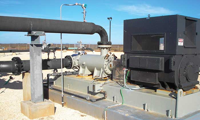 Image 1. Three-screw positive displacement pump in pipeline installation (Image courtesy of Circor)
- Viscosity =450 Saybolt Universal Seconds (SSU) (86 centistokes [cSt]): Use 60 mesh (0.010 inch, 0.25 millimeter [mm] opening)
- Viscosity >450 SSU (86 cSt): Use 40 mesh (0.017 inch, 0.42 mm opening)
- Viscosity >1000 SSU (216 cSt): Use 20 mesh (0.033 inch, 0.84 mm opening)
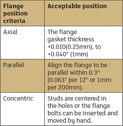 Table 1. Allowable piping misalignment
Foundation, Alignment & Rotation
It is hard to overemphasize the critical importance of a good quality foundation and grout installation to reliable long-term operation of the pump. There are plenty of resources (such as API RP 686 Chapter 5) to help. Refer also to the manufacturer’s installation, operation and maintenance manual (IOM) for specific guidance on the equipment requirements. Normally, the pipework should be connected and equipment should be aligned prior to grouting. Skipping this step can result in the need for expensive rework of the piping, baseplate machining or even the need to strip everything back and regrout. Never rely on the alignment that was produced where the pump and drive train were assembled. Transportation, lifting and handling as well as installation and grouting practices can all potentially affect alignment, usually in an undesirable way. Be sure to consider thermal expansion of the pump and driver when performing any shaft alignment. The manufacturer’s IOM should detail the offset values to consider when compensating for thermal growth during the alignment process.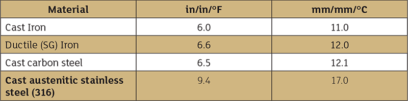 Table 2. Coefficient of thermal expansion for different materials
- Worked example (U.S. units) ambient temperature: 80 F
- Operating temperature: 224 F (driver, taken from the max temperature for Class B)
- Operating temperature: 100 F (pump)
- Material of construction: cast austenitic stainless steel (pump)
- Material of construction: cast steel (driver)
- CL height pump: 13 inches
- CL height driver: 11 inches
- Change at pump shaft due to temperature rise = 8.9 x10-6 x (100-80) x 13 inches = 0.002 inch
- Change at driver shaft due to temperature rise = 6.5 x10-6 x (224-80) x 11 inches = 0.010 inch
- Difference = 0.002 inch – 0.010 inch = -0.008 inch
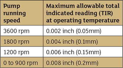 Table 3. Alignment values