When designing and installing a piping system for liquid service in industrial or commercial applications, the location and type of valve selected for process control plays a major role in whether the valve will operate smoothly or if it may experience cavitation or choked flow. These severe operating conditions may not only damage the valve and increase maintenance costs, they could also create safety hazards for the plant personnel. In addition, the severe conditions may impact the ability of the process to deliver the liquid at a designed flow rate, pressure, temperature or other quality parameter. Cavitation and choked flow conditions are difficult to recognize and can occur in any piping system. However, with a piping system model, a problem such as choked flow can easily be identified and solutions evaluated in the model prior to implementation. High temperature and high pressure drop applications make the valve more susceptible to cavitation and choked flow. Installing the valve at high elevations in the system where the inlet pressure of the valve is low may cause cavitation, which is unlikely if the valve is installed at a lower elevation. The type of valve selected also plays a role in determining whether the valve will operate with cavitation present or if the choked flow rate is reached.
Cavitation & Choked Flow
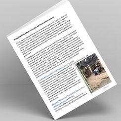
Cavitation is a condition that occurs when the pressure drop across a valve causes the fluid’s static pressure to drop to the vapor pressure and the liquid flashes into vapor bubbles. The area with the smallest flow passage in the valve, or the vena contracta, is the most susceptible location for cavitation to begin. This is the point of highest velocity and lowest pressure (Bernoulli principle in action). When the flow passage downstream of the vena contracta expands, some pressure recovery occurs as the fluid velocity decreases and pressure increases before it leaves the valve body. If the pressure increases above vapor pressure, the vapor bubbles collapse and implode on internal surfaces of the valve, damaging the material with each implosion.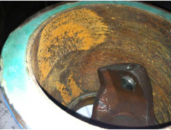 Image 1. Severe pitting damage from cavitation resulted in a pinhole leak on the valve body of a V-notch ball valve used to regulate the cooling water flow to aluminum casting molds. (Image courtesy of the author)
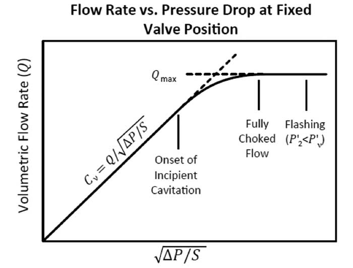 Image 2. Graph of flow rate versus the square root of the pressure drop across the valve (Image courtesy of Crane Technical Paper TP-410)
Deviation from Predicted Performance
When cavitation occurs in a control valve, the actual flow rate begins to deviate from what is predicted using the flow coefficient equation presented in the ISA standard for sizing control valves S75.01 (IEC 60534-2-1 equivalent). This is a result of the vapor bubbles occupying more volume as the mass of liquid expands during the phase change, creating an additional resistance to flow. As seen in Image 2, for a given valve position and flow coefficient (Cv), the valve’s performance begins to deviate from the linear relationship at the onset of incipient cavitation. If the flow rate or pressure drop required for the application is greater than the choked values, then the required flow or pressure drop will not be achieved, and the valve will be exposed to these extreme conditions. The liquid pressure recovery factor (FL) is an important characteristic of a control valve that roughly indicates how much pressure drop occurs across the valve compared to the pressure drop from the inlet to the vena contracta.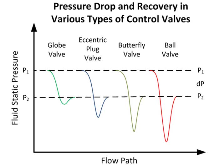 Image 3. Pressure profile for various types of valves for a given pressure drop
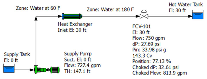 Image 4. Control valve at 30 feet elevation
Using a Model to Evaluate Choked Flow
A software simulating the system should display a warning when the conditions for choked flow are met. Consider the piping system modeled in Image 4. Cold water at 60 F is pumped to a heat exchanger and heated to 180 F. The flow rate is controlled by a globe valve type of flow control valve located at 30 feet of elevation. With this design, the control valve would operate at about 77 percent open at 750 gallons per minute (gpm) with a pressure drop of about 27.7 pounds per square inch (psi). Since the operating flow rate and dP are below the choked flow rate (813.9 gpm) and choked differential pressure (dP) (32.61 psi) values, the valve will not be choked and this system should operate as designed.Higher Elevations Increase Susceptibility to Choked Flow
Suppose a last-minute design modification was made after all the equipment was purchased and required the heat exchanger and control valve to be located at 45 feet elevation instead of 30 feet. Image 5 shows that this design change would result in choked flow at the control valve. What caused it to choke? Because of the higher elevation, the inlet pressure of the control valve is lower (pressure head is converted to elevation head per Bernoulli's principle). This reduces the choked dP and choked flow rate. Since the required dP across the control valve (27.49 psi) is greater than the choked dP (27.44 psi), the valve would operate under choked flow conditions at 750 gpm.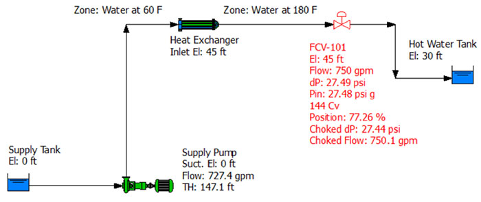 Image 5. This heat exchanger and control valve is located at an elevation of 45 feet. Choked flow is indicated.
Higher Temperatures Increase Susceptibility to Choked Flow
To evaluate the effect of fluid temperature on choked flow in a control valve, consider the same system in Image 5 with choked flow at the valve at the higher elevation and a higher fluid temperature. If the required fluid temperature was 150 F instead of 180 F, as shown in Image 6, the valve would not be choked and would deliver the fluid to the hot water tank at the designed flow rate of 750 gpm. Why is the valve not choked even when installed at the higher elevation?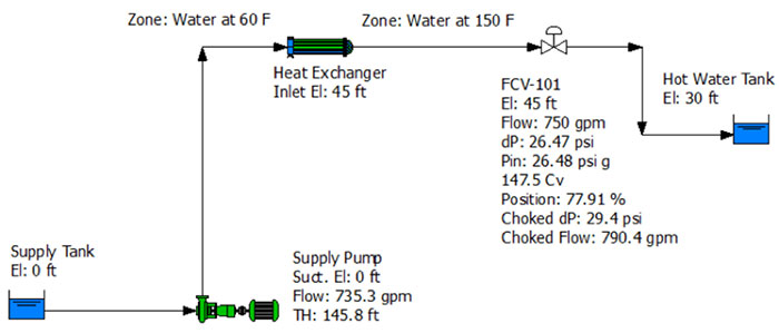 Image 6. Colder water does not result in choked flow, even with the valve at the higher elevation.
Valve Type Influences Susceptibility to Choked Flow
Different types of valves have different values of the FL based on the internal flow passages of the valve.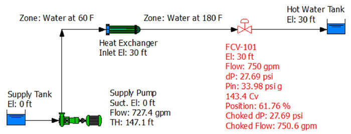 Image 7. A different control valve with a lower FL selected for the original system (valve at lower elevation with 180 F) results in choked flow.