10/13/2014
Centrifugal pumps often experience repeat failures. Maintenance and reliability professionals are charged with preventing them. This four-part series explains the reasons behind repeat pump failures and uses a real-world field example involving boiler feedwater (BFW) pumps. In last month’s column, I recommended best practices for pump rebuilding, lubricant selection, and coupling and seal maintenance. This last installment discusses bearings and pump reliability, focusing on additional equipment features. I will cover details such as sleeve bearing design, bearing cage materials and maintenance procedures.
Details Are Important
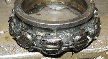
In the final analysis, understanding and working on details will eliminate repeat problems with centrifugal pumps. In the example that has been covered in this series, the team working on the system recognized that the braided packing installed at several of this facility’s 1950s vintage BFW pumps also provided shaft stabilizing. Eliminating the packing and replacing it with a mechanical seal could cause the first lateral critical speed to drop into the operating speed zone. Therefore, a suitable, high-performance polymer bushing had to be installed in the throat bushing space. This requirement explained why the refurbishing had to be entrusted to an experienced pump rebuilder. The facility was asked to determine if the babbitted sleeve bearings listed in the plant’s spare parts catalog were made with the proper grade of babbitt. At least three different babbitt grades are used in fluid machinery. The grades vary greatly in load-carrying capacity. The babbitt must be bonded to a substrate without liftoff or delamination. The adequacy and conformance of the existing spares should be verified by ultrasonic examination.Image 1. This riveted cage bearing failed because of axial (rotor thrust) overload. (Image courtesy of the author)
The team analyzing the failures also asked the facility to determine the sleeve bearing clearance, which was 0.001 mil per inch of diameter + 0.002 inch. For a 4-inch sleeve bearing, the clearance would be
0.004 + 0.002 = 0.006 inch.
One of the plant’s seven BFW pumps had a 17-4PH stainless steel shaft. For this pump, the allowable rolling element bearing inner ring-to-shaft interference fit was less than the more customary American Iron and Steel Institute (AISI) 4140 steel shafts in the other six pumps.
This subtle difference should be spelled out in a procedural document or checklist. The plant’s maintenance personnel should use this written documentation.
The documents used by plant personnel should be the same as those used by the rebuild shop that is selected to ensure that the old pumps are compliant with the best available technology. However, the pump that did not meet the AISI requirement also used a riveted steel cage bearing, similar to the one in Image 1.
Bearings with riveted steel cages were disallowed by experienced hydrocarbon processing plants around 1965 and by American Petroleum Institute (API) 610 around 1975. The small rivet heads of the two-piece steel cage are the weakest link. Historically, they often pop off and cause bearing seizure within seconds. API 610, therefore, stipulates that only bearings with brass or bronze cages should be used.
While recent advances in high-performance polymer (HPP) formulations make HPP feasible in certain pump applications, it would not be appropriate to simplify matters by allowing all types of plastic cages. Inexpensive cages may end up being trouble in certain applications. The good ones requested by reliability-focused plants will cost more money, but will also be worth the cost because of less downtime and fewer maintenance requirements.
The facility realized that work processes and procedures are often intertwined. With that in mind, the repair team recommended that this facility’s shop pay more attention to proper impeller removal and remounting steps. Removing impellers from multistage and deep-well pump rotors is best accomplished by suspending the rotor vertically. The first impeller is then heated from the outside toward its hub and allowed to drop into a sand box. The same heat-and-drop procedure is applied to the next impeller.
The analysis team was also made aware that this facility occasionally experienced cracked motor feet. In some facilities, sledge hammers are used to align equipment, which should never occur and may crack the motor’s feet. The team did not assume that plant personnel used sledge hammers. Instead, it turned its attention to the jack bolts, which were provided on many of the plant’s newer base plates to aid in maneuvering the pumps and drivers into alignment. The tip of each bolt needed to be backed away from engaging the equipment feet after alignment moves were complete. Using a piece of exact-thickness tool steel (about 0.125 inch thick) as a gauge between the tip of a jack bolt and an equipment foot would allow maintenance technicians to later determine if any of the feet moved more than others. The analysis team speculated that inappropriately spaced jack bolts explained at least one incident of fractured motor feet.
As a matter of routine, whenever or wherever the facility used constant level lubricators, these should be the balanced-pressure type. The ones recommended incorporated a vertically oriented sight glass. The balance piping should be liberally sized and go back into the bearing housing vent just below the desiccant breather. Small tubing may not serve as a reliable balance line because drops of oil will act as a liquid plug.
Regarding the desiccant cans, they no doubt removed moisture from air ingested through the vent, but they had not mitigated the root causes of the bearing failures. If bull’s-eye style sight glasses were to be installed, the analysis team recommended that the largest sight glasses available be used. They should then be installed (during pump rebuilding or upgrading) on opposite sides of the bearing housings. This would allow sunlight to assist in viewing the oil levels.
Sound Results
Because the analysis team wanted to be encouraging to the metal producer, the team assured the resident maintenance supervisors and reliability engineers that it had many positive findings. Most of what they were doing within the plant to maintain the equipment was good. Unlike the pump shown in Image 2, none of the metal producer’s seven BFW pumps required a radical redesign. However, plant personnel were asked to implement an electronic control strategy or an “operator alert” announcement system that ensured that each pump operated within 80 to 105 percent of its best efficiency point.Image 2. Pump upgrading by experts can result in efficiency gains, extended operating life and greatly reduced failure risk. (Image courtesy of HydroAire Inc.)
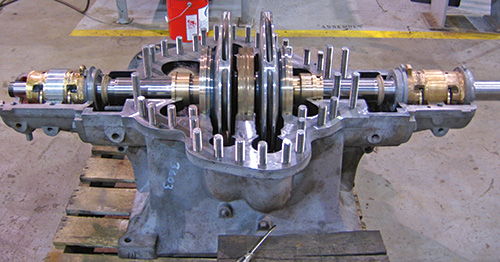
During the overhaul and restoration each pump, returning the clearances to original equipment manufacturer’s tolerances should be a priority. All upgrade measures or add-ons described in this series would further extend uptime and reduce failure risk at this facility.
The upgrades were far less expensive than the repeat failures and production interruptions. All the recommended upgrades were implemented at best-practice plants—some did so more than 30 years ago. Also, all upgrade measures were documented in texts. In some cases, a book can save a facility $50,000. This type of analysis and overhaul/repair should not be ignored, even if the facility always makes the Fortune 500 List.