Advances in seal ring and face materials can improve basic design issues associated with mechanical seals.

The mechanical seal was invented in the 1940s as a replacement for packings. The device needed to fit in the same cavity (i.e. the stuffing box) as the packing because of volume limitations. Advantages over packings included reduced wear against the pump shaft and elimination of the need to periodically tighten the packing nut to keep it tight against the shaft. Mechanical seals were more expensive, so the purchase cost had to be offset by low maintenance costs and increased life expectancy of the seal. Fast forward 75 years, and it is clear the mechanical seal has successfully met these challenges. As a result, mechanical seal design has not changed very much. One could argue that the basic design has not changed at all. The device is still basically two faces in sliding rotation relative to each other. They must be smooth, optically flat, and in parallel and close to one another. That last feature is where the "rub" comes in. Ring smoothness and flatness can be routinely accomplished in manufacturing. The parallel/proximity is determined by many factors including the seal assembly, the environment in which it operates and the size constraints of the stuffing box. Every seal application poses a different set of these circumstances to the rotating rings. Careful engineering is directed at the operating environment of sealed fluid, temperature, pressure, pump speed, seal configuration, seal ring material and its running surface characteristics. Balancing these competing parameters is essential to achieve the parallel/close proximity required for proper seal operation and wear life. Leakage is proportional to the proximity of the ring faces. If they remain parallel, a well-behaved hydrodynamic lubricating film will form between them with minimal leakage. Figure 1 shows a simple diagram of a single seal arrangement with a rotating primary ring. This seal is at rest—there is no fluid pressure nor rotation. In this state, the seal rings are parallel with and in proximity to each other; they are touching. When the seal is pressurized, the primary ring will deform under the pressure.
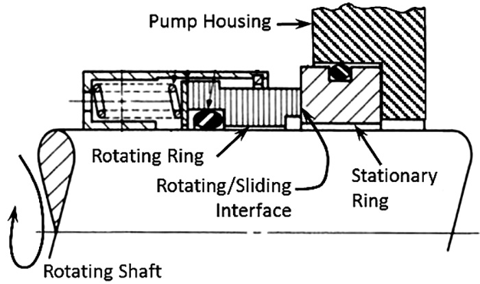
Figure 1. A diagram of a single mechanical seal at restFigure 1. A diagram of a single mechanical seal at rest (Graphics courtesy of Carbide Derivative Technologies Inc.)
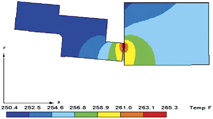
Two other effects happen when the seal rotates. First, the seal faces separate due to the effects of hydrodynamic lubrication (lift) caused by the pressure of the sealed fluid trying to escape through the gap. Second, friction causes the faces' temperature to increase, creating thermal deformation. Figure 2 shows how the seal faces can deform and the effects of temperature (see page 47). The rotating ring angle of deflection has been exaggerated to show where the two faces can be overstressed from operational effects. The real trick in all seal application engineering is to keep the sealing faces parallel and in close proximity. Figure 2 shows the two deleterious effects of getting this wrong. First, the pressure deformation causes a non-parallel situation called radial taper that will cause leakage. If this effect is large enough, the outer diameter edge of the rotating ring will come in direct contact with the stationary ring, violating the close proximity requirement. One can think contact means very close proximity, which is a good thing, but no lubricating film can be established in this condition, and the result is dry friction that can drastically reduce seal life. An area of temperature increase also results, which can be seen by the temperature contours. Thermal expansion will happen in this area and cause a dimensional increase in the ring surface (i.e. a bump) that worsens the premature wear.
Figure 2. Mechanical seal rings in operation with induced deformations from pressure and temperatureFigure 2. Mechanical seal rings in operation with induced deformations from pressure and temperature

Seal Ring & Face Materials

Decades ago, the prevailing wisdom was to combine a soft material that had some lubricating qualities and rotate against a harder material. This method was used specifically to cope with the situation shown in Figure 2. This situation would be mitigated after a certain period of "run-in," where the soft material was compliant and eventually wore at an angle to establish the necessary parallel condition. The worn-in angle would only be parallel at nominal operating conditions. Any process upset would disrupt the parallel situation, and the seal would leak. This issue led to extensive development of several grades of carbon, carbon phenolics and graphites that would run against hard materials such as tool steel, Stellite and tungsten carbide. Ceramics such as alumina were introduced, and later silicon carbide. Until the 1990s, combining hard materials against themselves or other hard materials was considered impossible because they were not able to withstand the operating deformations without damage. In a process upset, the contacting edge of the deformed ring could machine itself into its counterface, causing catastrophic failure. Sophisticated computing technology and finite element modeling enabled engineers to make more precise application calculations and control designs to more accurately establish the parallel/proximity of the sealing faces in operation. Silicon carbide was also being perfected, and its hardness—next to that of diamond—helped to increase seal life through reduced wear. Finite element modeling enabled engineers to combine it against itself with confidence that it would operate with adequate parallelism and lubrication. After 20 years of application experience, silicon carbide against itself has become a standard seal ring combination in industrial applications.

Industry Advances

The next levels of seal performance improvement beyond silicon carbide included diamond coatings, which were the only material harder than silicon carbide. Industrial diamond coatings emerged in the 1990s with varying degrees of success. Early applications to mechanical seals were plagued by adhesion failures and surface morphologies that were more applicable to cutting tools. Adhesion risk is inherent when a coating of one material is applied to a substrate of a different material due to the adhesion between them at the bond line, plus differences in their thermal expansion coefficients. The mechanical stress on the adhesive bond line from operation (in Figure 2) combined with the thermal expansion differences can cause delamination. Other state-of-the-art surface treatments include those not involving a coating process. One treatment starts with a finished silicon carbide component and involves etching the silicon out of the carbide surface, leaving the carbon behind. Because no dissimilar material is added, there is no adhesive bond line, and the resulting part is dimensionally the same as before treatment. A cross section of treated surface can show where the treatment undergoes a natural transition into the carbide substrate, with no adhesive bond line and no stress concentrations. The microstructure is not disturbed in this process, and it is as strong as when originally sintered. A unique aspect of this new surface is that it is functionally graded, not homogeneous. The first several microns are composed mostly of graphite and free carbon. Closer to the transition to the virgin carbide, nanocrystalline diamond emerges, mixed with the graphite and carbon. The result is a hard component with a hard surface that is also self-lubricating, compliant and able to deal with the radial taper that results from the process upset shown in Figure 2. It basically gives the best of both hard and soft surfaces without delamination risk. In one case, only 1.7 micrometers (µ5m) of wear resulted from a 100-hour accelerated wear test in flashing hot water that caused 190 µ5m of damage to an untreated silicon carbide ring. Similar tests have resulted in no measurable wear, while also exhibiting the unique ability of this surface to self-polish. The self-lubricating qualities enable dry gas seals to withstand the dry running conditions involved with start/stop, reverse rotation and slow roll. New surface treatments present a paradigm shift because they are not homogeneous and do not involve adhesion mechanisms. The non-homogeneity provides self-lubricating compliance in both nominal and process upset conditions, including flashing or dry running. Such performance overcomes the most significant sealing challenges that impact mean time between failures and mean time between maintenance. They are also amenable to batch processing in large quantities, which enables widespread application at an affordable cost.

Issue