In recent years, most industry professionals have been leaving the decision of driver size selection to pump-selection software. There is nothing wrong with that choice, and many selection software programs do a great job. This column will explore some of the specifications and decision-making processes that occur behind the scenes. I offer this information because I have witnessed several poor decisions in recent years with regards to driver selection and sizing. It is a delicate balancing act fraught with compromises to properly size a motor as a pump driver. Too big and you waste money in the initial cost and over the life of the unit because it manifests as inefficiency. Too small and you will reduce the life of the motor. Overloaded motors will run hot and fail the insulation system. Just an 18 degree Fahrenheit increase in normal winding temperatures will reduce the insulation life by 50 percent. In most cases the pump driver will be an alternating current (AC) electric induction motor or an internal combustion engine. When quality steam is available and the duty cycle is approaching 100 percent, turbines are an efficient driver choice, especially in the larger horsepower (HP) ranges above standard National Electrical Manufacturers Association (NEMA) frame sizes.
Making a Choice
Let’s start with a simple pump curve and select the correct driver based on the rated hydraulic conditions. Refer to the pump curve (Figure 1, page 23). The rated hydraulic conditions for the example pump are 270 gallons per minute (gpm) at 115 feet of total dynamic head (TDH) pumping clear water at an ambient temperature of 68 F with a specific gravity of 1.0 and viscosity of 1 centipoise. Unless the curve states otherwise, most every pump performance curve is based on clean water at 60 or 68 F with a 1.0 specific gravity and a viscosity below 5 centipoise. The example pump is an end suction American National Standards Institute (ANSI) pump of size 2 x 3 x 6 operating at 3,550 rpm with the impeller trimmed to 5.5 inches. I have simplified the curve as much as possible for this example (efficiency at the duty point is 77 percent). Note that the pump will require 10.2 brake horsepower (BHP) at the duty point also known as the rated point. I used the basic horsepower formula (see Equation 1) to arrive at that number, which corresponds with the selection software. The program selects a 20 HP motor for the condition because I have the software sizing criteria set to select a motor for the maximum power on the design curve (an industry best practice).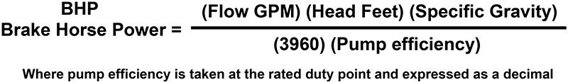
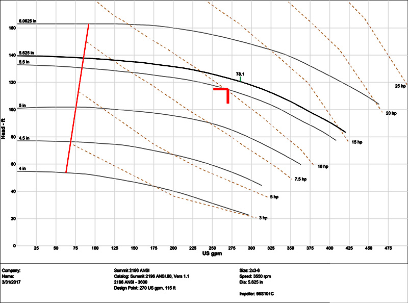 Figure 1. Pump curve (Courtesy of the author)