Positive displacement pumps effectively pump fluid at a constant average flow rate. However, because the individual pumping elements of these pumps discharge discrete quantities of fluid, the instantaneous flow rate varies in a cyclic fashion. Pulsations are observed in the system as pressure spikes. In the positive displacement pump family, single-shoe peristaltic pumps generally create the largest pulse, followed by two-shoe peristaltic pumps. Triplex and quintuplex pumps have smooth output curves because of piston overlap. Gear pumps can have extremely small pulses, but pulsations still exist. This pulsating flow can cause operational problems and shorten equipment’s service life. To alleviate the problem, pulsation dampeners can be added to the pumping system to absorb pressure spikes and smooth fluid flow. Figure 1 shows the undampened pressure spikes from a triplex pump in green. The dampened pressure curve from the same pump with the same system settings are indicated in blue. Six pulses per revolution occur instead of the expected three. This is a result of piston overlap.
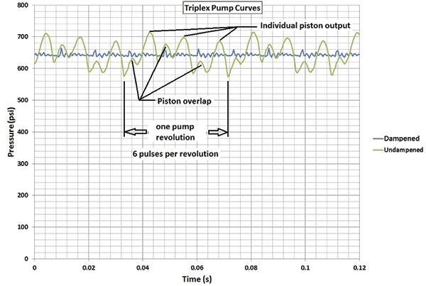 Figure 1. Triplex pump output pressure curves
Determine Adequate Size
The most common type of pulsation dampener is a hydro-pneumatic pressure vessel containing compressed air or nitrogen and a bladder—or bellows—that separate the process fluid from the gas charge. To maximize the dampening effect, pulsation dampeners should be installed as close as possible to the pump discharge with a gas charge that is slightly below the normal system pressure. More important, pulsation dampeners must be properly sized for the system. A dampener that is undersized cannot adequately compensate for pressure and flow fluctuations. An oversized dampener will act as an accumulator, storing too much fluid. This will cause slow stabilization and a delayed response to system changes. The first step in sizing a dampener is to quantitatively define the acceptable performance.Determine the Amount of Tolerable Pressure Variation
The specific requirements of the application and the components that make up the system are all factors that need to be considered. Once an acceptable pressure variation is defined, the unit size required for the desired performance should be determined. Engineers and designers are interested in making accurate predictions. Avoiding a problem is better than finding a way to fix it.Calculate Pressure Fluctuations
Sizing pulsation dampeners is straightforward. However, calculating the system pressure fluctuations is more complex. Fluid discharge rates from pumps are difficult to mathematically model. For example, in Figure 1, the spikes are not even. Theoretically, they should be equal. Mathematical models must be physically tested to verify their accuracy. Pumps with multiple heads and higher pulse frequencies can make the calculations more difficult. The distance from one output port to the next is generally not constant. This creates a shift in the piston overlap with intermittent larger and smaller pulses. Calculating the magnitude or frequency of noise pulses that can develop or resonate in a system is difficult. Piping arrangement—such as bends, reducers and valves—combined with the opening and closing of pump discharge check valves can create noise in the fluid called pressure pulses. Because many variables must be considered, each pump type should be tested with and without a dampener. The pressure curve data can be recorded and used to find the pump’s formula constant. This constant can be used in future calculations. As long as other pump models are similar to the test unit, accurately predicting the magnitude of line pressure variation with a given size dampener is possible.Minimize Acceleration Head
The pressure in a piping system will rise sharply when a volume of fluid is added to the line. It accelerates the mass of the fluid in the piping system. This is acceleration head, and it needs to be minimized with a dampener. The effect and its impact must be considered on both the inlets and outlets of positive displacement pumps. On the inlet side, cavitation and partial filling of pump cavities can damage pump components and make the pump much louder than normal. A non-snubbed pressure transducer can accurately measure the system’s pressure spikes. A pressure transducer can react much faster than a bourdon tube gauge, and it can measure noise if the sample rate is high enough. Bourdon tube gauges require time to equalize and can undershoot and overshoot the actual pressure depending on the magnitude and frequency of the pressure pulse. Even if the gauge could read accurately, reading a quickly moving dial is difficult. Electronically measured and recorded data can determine how the system is operating. System noise must be considered when taking measurements because it can give higher-than-expected results. Noise in the pumping liquid can generally be ignored, but in some situations, system noise needs to be controlled. Noise can cause pressure relief valves to leak, damage sensitive components and create occupational safety hazards. Dampeners typically reduce noise, and some are specifically designed for this purpose.Pulsation Dampener Styles
Several different styles of dampeners are available, and each has advantages and disadvantages. This article focuses on reducing the pressure pulses caused by pulsing flow. The principles and the method for calculating the appropriate size dampener for this application are the same for most dampeners. A dampener absorbs a fluid pulse and then allows the fluid to flow back into the system between pulses. Most dampeners use a gas charge that is set slightly below the normal system pressure and is compressed by the pulse of fluid. The gas then expands when fluid is released.Calculate Pressure Changes
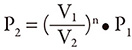
Two formulas should be considered when calculating pressure changes in the gas: If the pressure changes happen slowly, the gas temperature will have time to equalize. This is an isothermal process. The equation is: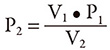 Where P1 and V1 are the initial states, and P2 and V2 are the final states.
The other formula assumes no heat transfer from the gas to its surroundings. This is an isentropic process, and the equation is:
Where P1 and V1 are the initial states, and P2 and V2 are the final states.
The other formula assumes no heat transfer from the gas to its surroundings. This is an isentropic process, and the equation is:
 In this formula, n is a constant that is specific to the gas being used. For example, for air at room temperature,
n ≅ 1.4, and for nitrogen, n ≅ 1.399.
Some heat transfer almost always occurs. The process is rarely slow enough for the gas temperature to equalize, so the actual answer will be between these two calculations. In most cases, the fluctuations are fast enough that the actual value is significantly closer to the isentropic formula. The isentropic formula gives the most conservative result. Therefore, it is the more accurate formula in most cases.
In actual practice, either formula would probably work if the pressure fluctuations are small relative to the system pressure. The pump constant that is developed would cover the inaccuracies in the formula as long as the pressure variations are similar. In this article, the isentropic formula is used.
In this formula, n is a constant that is specific to the gas being used. For example, for air at room temperature,
n ≅ 1.4, and for nitrogen, n ≅ 1.399.
Some heat transfer almost always occurs. The process is rarely slow enough for the gas temperature to equalize, so the actual answer will be between these two calculations. In most cases, the fluctuations are fast enough that the actual value is significantly closer to the isentropic formula. The isentropic formula gives the most conservative result. Therefore, it is the more accurate formula in most cases.
In actual practice, either formula would probably work if the pressure fluctuations are small relative to the system pressure. The pump constant that is developed would cover the inaccuracies in the formula as long as the pressure variations are similar. In this article, the isentropic formula is used.
Determine the Pump Constant
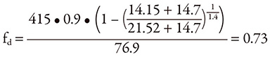
To determine the pump constant, the volume from a single pulse of the pump must first be determined. Then an initial estimate of dampener size is made, and the corresponding value of dampener volume is applied. The amount of gas in the dampener will be less than the total dampener volume, which needs to be factored into the calculation. A typical range of 80 to 90 percent of the dampener volume should be gas if the dampener is properly charged. These give an initial gas volume: (Vp = pulse volume) (Vd = dampener volume) (Vpr = percent fill) V1 = Vd • Vpr The final volume is the initial gas volume minus the pulse volume: V2 = V1 – Vp The constant reduces the pulse volume to account for flow leaving the dampener while the pulse is entering. It also accounts for piston overlap, which changes the effective size of the pulse. Adding the factor to the isentropic formula and solving for the pump factor gives us the following equation: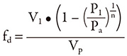 Where:
fd = pump factor constant
Pa = measured maximum absolute pressure
P1 = minimum absolute line pressure
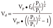
The pressure formula can be rearranged to give the desired dampener volume with given minimum and maximum pressures:
Where:
fd = pump factor constant
Pa = measured maximum absolute pressure
P1 = minimum absolute line pressure
The pressure formula can be rearranged to give the desired dampener volume with given minimum and maximum pressures:
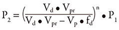
 The formula can also be rearranged to give pressure variation with the pump factor and with a known dampener volume:
 Note: The formula does not account for pressure spikes that result from rapidly changing the flow rate in the piping system. These pressure spikes, also known as water hammer, can travel throughout the entire piping system and may damage pumps, piping and other fixtures. If this type of pressure transient occurs in the system, a larger dampener at the pump may be needed. Alternatively, an additional dampener at the source of the transient spike may be required.
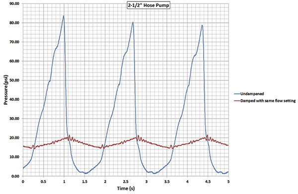 Figure 2. Peristaltic pump pressure curves
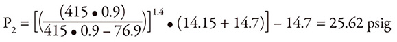 It is important to remember to add 14.7 psi to convert from gauge to absolute pressure, then subtract 14.7 psi again to get the final result in gauge pressure. This pump setup was tested, and the actual pressure variation was determined to be 7.38 psi. Therefore, the result is:
Pa = 7.38 + 14.15 = 21.53 psig
Inserting the numbers into the factor formula gives:
It is important to remember to add 14.7 psi to convert from gauge to absolute pressure, then subtract 14.7 psi again to get the final result in gauge pressure. This pump setup was tested, and the actual pressure variation was determined to be 7.38 psi. Therefore, the result is:
Pa = 7.38 + 14.15 = 21.53 psig
Inserting the numbers into the factor formula gives:
 If the example above is used and it is decided that a pressure fluctuation of 15 psi would be acceptable, the formula with the previously calculated pump factor can be used to determine what size of dampener is needed.
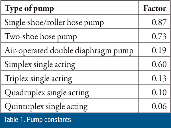
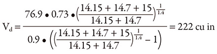 Table 1 lists some approximate pump constant factors that can be used when sizing dampeners for different pump types. These factors are approximate, and the results may vary significantly with the many variables involved.