
Vibration and maintenance were reduced with the installation of carefully selected equipment.
05/22/2014
A service provider operates a sludge drying facility that is located within the Stickney Water Reclamation Plant for the Metropolitan Water Reclamation District of Greater Chicago (MWRDGC) in Cicero, Ill. The facility, which processes wet sludge into dried pellets for use as an agricultural and commercial fertilizer product, represents one process of the overall plant. The drying and pelletizing occurs in a pelletizer that indirectly heats the sludge using hot oil pumped through a series of trays at more than 570 F.
Hot Oil Pump
The hot oil pump operates at an oil temperature of 570 F, while the motor is at ambient temperature. The coupling alignment is difficult to set and must be completed when the pump and motor are cold and again when hot because of the effects of thermal expansion. The pumps had an initial running vibration of more than 0.25 inch per second (in/sec). A 0.1 in/sec measurement would be the maximum acceptable vibration and it is recommended that vibration is less than 0.05 in/sec for a significant improvement in reliability. Typical failures included mechanical pump seals, valves, drain plugs and flanges—which were all leaking oil. Because of the oil’s temperature, many of these failures resulted in smoke because the oil started to burn upon leaking. The high vibration and load stress resulting from the thermal-expansion-driven misalignment was causing particularly high failure rates for the No. 4 pump, the primary thermal oil supply pump. This pump had a significant number of failures and had to be rebuilt three times in 18 months according to records in the computerized maintenance management system.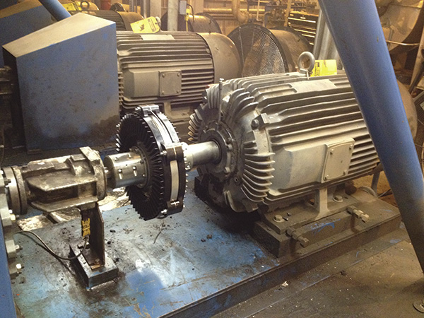 Image 2. The installed magnetic coupling
Coupling Alternatives
Because of the ongoing misalignment-related issues, facility management researched the latest in flexible coupling technology. Each coupling type reviewed for the hot oil pump had distinct pros and cons. Fixed, direct and rigid style couplings suffered from the transfer of vibration and axial loading when thermal growth of the pump shaft occurred, causing perpendicular stress loading on the motor and pump axial bearings. Traditional flexible couplings (for example, elastomeric, grid or gear) provided some axial load relief but did not resolve the parallel misalignment created as the pump base and structure experienced vertical growth with increased temperature. The vertical misalignment caused torsional loads on the motor and pump bearings, in addition to loads on the coupling that caused vibration of the motor and pump. Finally, magnetic couplings were considered. Magnetic couplings are ideal for a hot oil pump application because no physical contact between the motor and load is allowed. The magnetic air gap provides enough clearance to allow for vertical and axial changes in dimension to occur without impacting the coupling’s torque transfer, and vibration cannot be transmitted between the load and motor. The air gap also provides a thermal break that protects the motor from the extreme heat of the pump and acts as a shear pin during a load seizure, protecting shafts and connected equipment from severe damage. However, potential limitations in magnetic technologies had to be addressed. First, axial thrust and end play on either the motor or pump could be a concern because magnetic couplings could allow too much movement in the axial direction. Second, during a load seizure, the magnetic coupling must transfer enough torque to automatically cause the motor overload circuits to trip and shut down the system to protect the magnetic coupling from damage caused by overheating.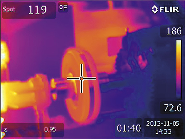 Image 1. Infrared image showing the thermal isolation
Magnetic Coupling Selection
Based on a review of the available technologies, magnetic couplings provided the best combination of performance and benefits for the hot oil pump system. However, the evaluation and selection criteria for a magnetic coupling for the hot oil pump application were critical. The coupling needed to meet all performance requirements and had to fit within the existing motor and pump with minimal rework. Because a locked rotor condition (resulting from a seized pump bearing or failed impeller) can create an overheating hazard that can damage the coupling, selecting a magnetic coupling that can transfer more than full-rated torque during locked rotor conditions was important. By doing so, the coupling will cause an increase in motor amperage inside the motor starter for a measurable time, allowing the motor’s protective circuitry to automatically disconnect power. Axial end play concerns also needed to be addressed because thrust inside the motor housing may cause axial movement in the motor rotor and shaft, particularly in rebuilt motors that may not meet original manufacturing specifications. Ultimately, a new type magnetic coupling based on induction rotor technology was selected. This technology has the following characteristics:- A minimum misalignment tolerance of 0.1 inch in any direction because of the air gap between the motor and load
- Fits within American National Standards Institute and National Electrical Manufacturers Association standard dimensions so no modification to the motor, pump or base required
- Transfers 125 horsepower at 1,800 rpm
- Provides transfer of 140 percent of full load torque in a locked rotor condition, leading to a 140-percent to 150-percent increase in motor current, which can be detected using a current sensing relay set to trip after a user-adjustable duration (typically 20 to 40 seconds)
 Figure 1. Comparison between induction rotor and eddy-current magnetic coupling designs
Installation
Prior to the installation, a new/rebuilt rotating assembly was installed in the pump. While the rated capacity of the motor on this system is 125 horsepower, historic power readings and pump curves indicated that this pump was operating at approximately 95 horsepower at the time of installation. The coupling was installed with the induction rotor mounted to the motor shaft, and the magnet rotor was connected to the pump shaft. The standard air gap between these coupling halves is 0.1 inch per side with no additional shims installed. However, one problem that was encountered during the installation was 0.03 inch of axial movement in the motor shaft. Given this axial movement and the known levels of additional thermal shaft growth, an additional 0.05-inch air gap spacer shim was inserted. The total available air gap was increased to 0.125 inch on each side of the magnet rotor, and this increase had a negligible impact on the pump speed.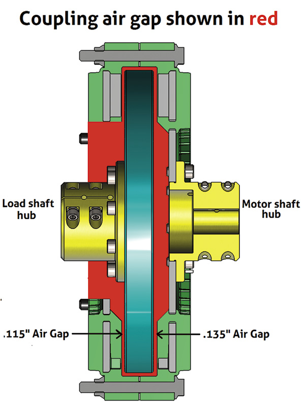 Figure 2. Air gap cross section drawing
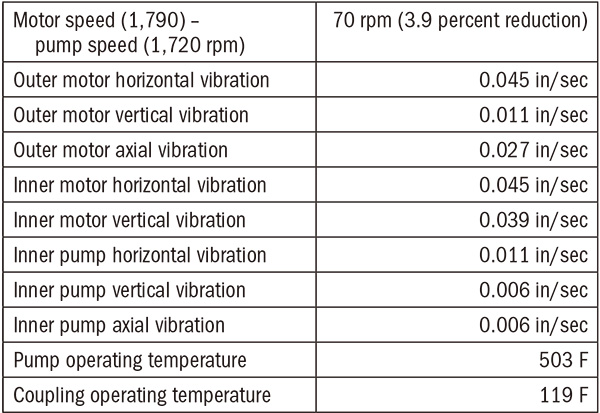 Table 1. Post-installation operation data