Vertical pumps are especially susceptible to minor conditions that can result in elevated vibration amplitudes. The vertically suspended design and long stationary element lengths often combine into natural frequencies that are near forcing frequencies, such as running speed or even subsynchronous faults. The complexity of these issues makes it difficult to diagnose and resolve persistent vibration issues with the type of data that is routinely available to end users.
In-depth field testing paired with computational analysis provides a clear path to both an accurate diagnosis and a solution that has a high likelihood of success. The effectiveness of this methodology was proven for a Gulf Coast midstream company that was experiencing high vibration with its vertical freshwater pumps. By applying advanced field diagnostics, the end user was able to understand the underlying causes of the vibration and evaluate possible solutions in a theoretical environment prior to implementing them in the field.
First Steps
A midstream fractionation and petrochemical complex had several 15-stage vertical can pumps with a long and complex history of high vibration. The vibration was severe enough to impact equipment operation due to forced high amplitude trips by system controls. Site engineering recognized that the vibration data and analytical capabilities they had in-house were not sufficient to confidently diagnose and resolve the issue. They contacted the field engineering division of an independent pump aftermarket company to travel on-site and perform in-depth field analysis as a first step toward understanding the root cause of
the problem.
The initial project scope included vibration testing during normal operation, completing an operating deflection shape (ODS) test to evaluate any mechanical faults that might be present and completing modal analysis testing to identify the natural frequencies present, their associated mode shapes and the proximity of the structural modes to known forcing functions.
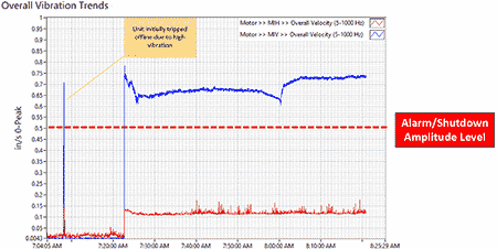
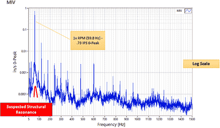
During the testing, vibration amplitudes were found to exceed 0.7 inches per second (IPS) 0-Peak (with the majority of the vibratory energy at 1x rotations per minute [rpm] or 59.8 hertz [Hz]). One unique caveat was that the highest vibration amplitudes were found at the lower motor mounting flange or drive end of the vertical motor. The elevated vibration was highly directional, and the possibility of resonant excitation was considered.
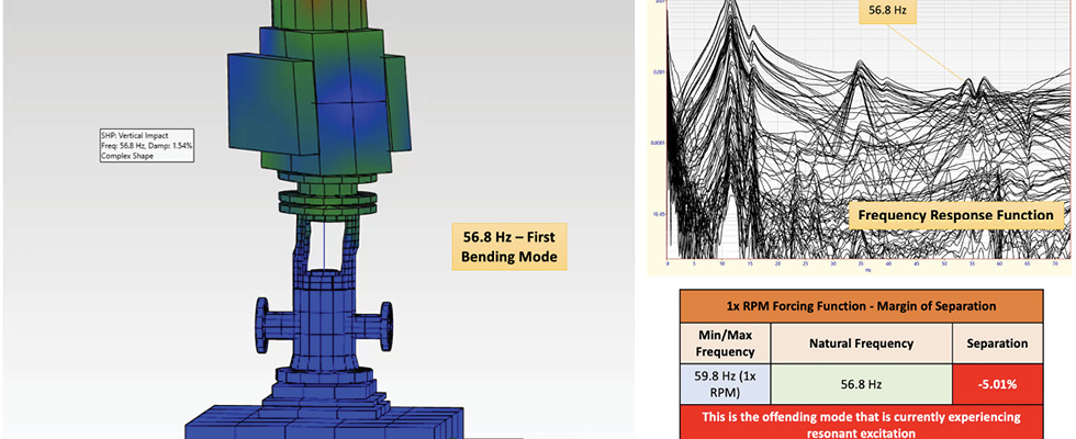
A 1:1 scale model of the installation was created in ME Scope software for use during the operating deflection shape (ODS) and modal analysis (EMA). While no mechanical faults (i.e., pipe strain, soft connection, etc.) were identified, the ODS showed a deformation of the pump and discharge head assembly similar to that of a first bending mode (“C” shape deformation) with the highest amplitude at the lower motor mounting flange.
The subsequent modal analysis performed confirmed the presence of a structural natural frequency (first bending mode) located at 56.8 Hz, having only a -5.01% margin of separation from 1x rpm. As a general rule of thumb, a +/-15% margin of separation between any natural frequency and forcing frequency is typically required to prevent resonant excitation.
Following the verification that the high vibration was due to excitation of a structural mode, several options were discussed with the end user. It is commonly understood that changes to either mass or stiffness would be required to “shift” the offending natural frequency outside the range of excitation.
The possibility of adding mass to the structure was discussed; however, another natural frequency (65.3 Hz, secondary bending mode) was found to be located just above the offending mode (56.8 Hz). Concern existed that the addition of mass might shift the primary offending mode lower and outside the range of excitation but could potentially “drag” the 65.3 Hz mode into excitation unintentionally. Additionally, the geometry of the motor made it difficult to add the amount of
mass that would be required, so this option was declined.
The use of a dynamic vibration absorber (DVA) was also discussed. A DVA is a tuned mass absorber that is designed to have the same natural frequency as the structure. When this device is placed into service, it vibrates in opposing phase from the resonant component(s), thereby canceling out the resonant excitation. Because space and size limitations were a concern with this option, as well as the fact that a DVA has the potential to “drift” in frequency over time, requiring periodic retuning, the end user decided against this option.
Site personnel and the field engineering specialists determined that a more in-depth analysis was necessary to determine the best path forward. The field engineering team proposed performing finite element analysis (FEA), which would allow them to implement structural modifications within the computational model that were cost-effective and efficient while minimizing trial and error in the field.
Model Development & Manipulation
The aftermarket service provider’s field engineering team created a solid model of the motor, pump discharge head, columns, bowls, suction bell and foundation. A coarse mesh was applied to the model and boundary conditions were then assigned. Only minor modifications were required to be made to the FEA model in order to have the predicted modes be equal to the real-world natural frequencies.
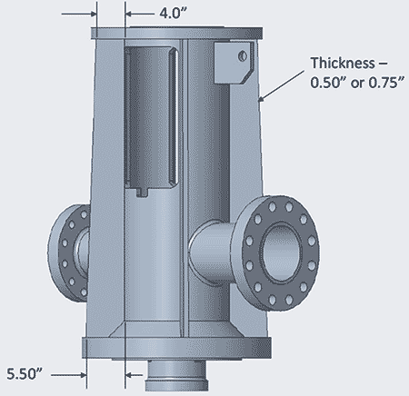
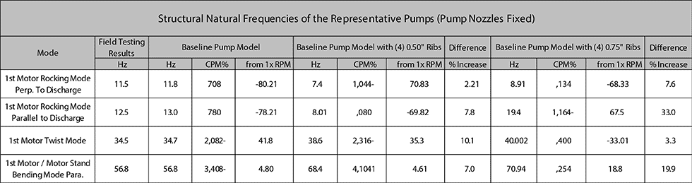
The FEA model was then manipulated with different modifications with the intention of shifting the offending natural frequency at 56.8 Hz to a margin of ~15% while maintaining a safe margin of the other natural frequencies. It was determined that the best method for reducing the resonant excitation was to add four stiffening ribs to the discharge head. This modification was evaluated with both four 0.50-inch thick ribs and four 0.75-inch ribs, and the resulting separation margins were calculated for both scenarios.
The 0.50-inch ribs were predicted to shift the offending mode from 56.8 Hz to 68.4 Hz, which represents a 14.6% margin from the running speed of 59.7 Hz (3,580 rpm). The 0.75-inch ribs were predicted to shift the suspected offending mode to 70.9 Hz for an 18.8% margin from running speed. In both cases, other natural frequencies maintained a safe margin from any forcing frequencies. Given the 0.75-inch stiffening ribs provided the greatest margin of separation, this option was chosen by the end user.
Final Outcomes
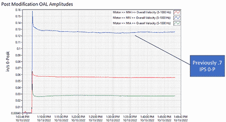
Following the workshop implementation of the stiffening ribs, another round of field testing was performed after the modification was completed to test the efficacy of the solution. The vibration had reduced from 0.6 IPS 0-Peak to a value of 0.30 IPS 0-Peak at the top of the motor and from 0.7 IPS 0-Peak to 0.13 IPS 0-Peak at the bottom of the motor. Post-modification impact testing verified that the natural frequencies of the structures had moved as predicted in the model, with the offending mode moving to approximately 70 Hz.
Although solutions designed during the FEA shifted the natural frequency outside the range of excitation, the vibration amplitudes were still nearly at the first amplitude alarm level. Additional analysis would still be required to try to further lower the vibration as the resonant excitation was no longer occurring.
The majority of the vibratory energy was still found to be occurring at 1x rpm (59.8 Hz); however, the highest amplitude vibration was now present at the top of the structure (motor). Cross channel phase data was collected at 1x rpm between the motor outboard horizontal (MOH) and motor outboard vertical (MOV) directions at the top of the motor and the motor inboard horizontal (MIH) and motor inboard vertical (MIV) directions at the bottom of the motor. Cross channel phase values (at 1x rpm) were found to be 92.39° at the upper motor measurement positions and 90.8° at the lower motor measurement locations. When elevated levels of residual imbalance are present in this type of vertical machine, a cross channel phase value at 1x rpm will be either 90° or 270° (+/- 30°). Given the results of this analysis, it appeared that elevated levels of residual imbalance were present within the coupled rotor.
It was recommended to remove the coupling assembly and balance the complete assembly to 1x weigh/speed (w/n), with the possibility of having to field balance the motor should the vibration amplitudes remain elevated after the coupling assembly was balanced and returned to service.
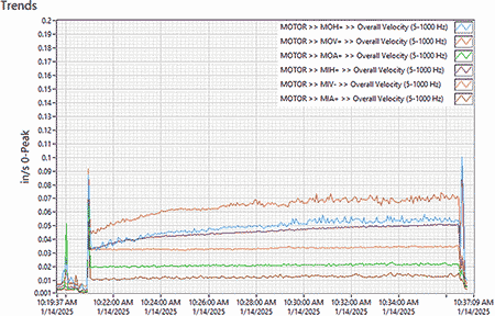
The aftermarket service company mandrel balanced the coupling assembly as specified in their Houston facility, and post-balancing vibration data was later taken in the field. Following the coupling assembly being balanced to 1 w/n, the 0.30 IPS 0-Peak vibration at the top of the motor was reduced to slightly below 0.08 IPS 0-Peak overall. Because the reduction of vibration was so successful, additional field balancing of the motor was deemed unnecessary.
This case demonstrates the powerful tools available to the rotating equipment industry for diagnosing complex vibration problems. By capturing comprehensive field data and applying the appropriate analytical tools, the site and end user were able to avoid costly trial-and-error methods and effectively eliminate the conditions that were preventing the subject equipment from operating reliably.