Q. What is a rotodynamic vertical pump? What pumps are classified in this way?
A. Rotodynamic pumps are kinetic machines in which energy is continuously imparted to the pumped fluid by using a rotating impeller, propeller or rotor. The most common types of rotodynamic pumps are centrifugal (radial flow), modified radial flow (turbine pumps), mixed flow and axial flow (propeller pumps).
These pumps, particularly the radial flow and modified radial flow types, are usually designed for multistage operation, by bolting or threading individual bowls together. The pumping element (bowl assembly) is usually suspended by a column pipe, which also carries the liquid from the bowl (assembly) to the discharge opening.
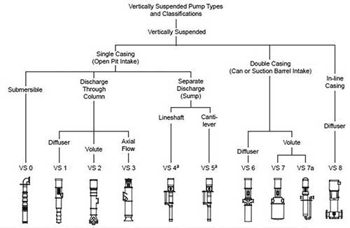
Rotodynamic vertical pumps (see Figure 2.1.3) are normally classified as deep well, short set or submersible motor-driven. The driver for these pump configurations is mounted either on the discharge head (lineshaft pumps); directly to the bowl assembly, either above or below (for pumps with submersible motors); or in a horizontal configuration, such as an electrical motor or engine, driving through a right-angle gear.
For more information about rotodynamic vertical pumps, see ANSI 2.1-2.2 Rotodynamic (Vertical) Pumps for Nomenclature and Definitions. P&S
 |
| Figure 2.1.3. Vertical pump types—vertically suspended, single & multistage |
Q. What considerations should be made for outdoor rotodynamic pump installations?
A. For outdoor installations, the pump components should be covered with rainproof tarps during installation to protect them from the elements. This is particularly important during freezing conditions to prevent water from collecting in pump cavities and causing freezing damage.
The pump and equipment, as shipped, have adequate protection for short-term storage (up to three months) in a covered, dry and ventilated location at the jobsite prior to installation. However, if the equipment will be subjected to extended storage (more than three months), then the standard warranty of the equipment may be affected. In this case, the equipment manufacturer should be advised about the extended storage duration when the pump is specified and/or ordered so that special, long-term storage protection can be provided before shipment to the jobsite.
For pumps that require onsite assembly, a clean, drained area should be provided next to the point of installation. The area should be of adequate size for placing the pump components and driver in the sequence in which they will be installed. Protective covers should be left on all pump openings until actual installation to prevent dirt and foreign objects from entering the pump. Protective coatings should likewise be left on machined surfaces to prevent rusting.
All pumps require regular maintenance. Therefore, the location of all pump discharge piping (and suction piping when applicable), auxiliary equipment, and control and starting panels should provide adequate access for maintenance. Suitable floor space and working room should also be provided for repair, including parts placement.
To minimize frictional head loss, the pump should be located where it can be installed with a short and direct discharge pipe and with the least number of elbows and fittings. If practical, it should be placed so that it will be accessible for inspection during operation. In addition, the equipment selected should be compatible with the environment. Pumps and drivers (other than submersible types)and controls should be protected against flooding. If ever in doubt, end users should refer to the manufacturers’ installation, operation and maintenance (IOM) manuals for IOM information specific to their equipment.
For more information on installation considerations for rotodynamic pumps, see ANSI/HI 1.4 Rotodynamic (Centrifugal) Pumps for Manuals Describing Installation, Operation, and Maintenance. P&S
Q. What is droop, and does it affect rotodynamic pump operation?
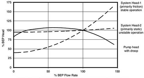
A. Some rotodynamic pump head versus rate-of-flow curves exhibit a characteristic commonly referred to as droop (see Figure 9.6.3.3.8a).
 |
Figure 9.6.3.3.8a. Pump head versus rate-of-flow curve illustrating a droop |
A drooping head versus rate-of-flow curve is one in which the zero rate of flow head (shutoff head) is lower than the maximum head on the curve.
This phenomenon often occurs in low- to medium-specific-speed pumps:
Specific speed (Ns) < 68 (Ns < 3,500)
These pumps have been designed to optimize efficiency. Droop does not present an application problem unless one or more of the following conditions exist:
The system head curve intersects the pump curve at two or more rates of flow.
The pump is operated in parallel with one or more other pumps at a system head that is greater than the pump shutoff head.
A continuously rising curve is required for control purposes. For example, systems that require pressure control.
Applying pumps with drooping head curves in these conditions may cause the pump to be pushed back to shutoff or to “hunt” between two operating points. Neither condition is desirable. In these cases, the allowable operating region may require further limitation and/or appropriate system controls may be implemented. In the absence of any of the above conditions, pumps with drooping head curves can perform as well as pumps with continually rising curves.
For more information about rotodynamic pump operating conditions, see ANSI/HI 9.6.3 Rotodynamic (Centrifugal and Vertical) Pumps – Guideline for Allowable Operating Region. P&S

