
02/17/2015
In 2014, this column focused on improving the operation of piping systems by performing pumped system assessments. The columns have covered energy cost balance sheets, the assessment process and the performance of sample assessments. By now, readers are aware that all the equipment found in a piping system falls into one of three categories:
- Pump elements add all the fluid energy to the piping systems.
- Process elements are used to make the product or provide the service.
- Control elements are used to improve the quality of the product or service.
Why Pumps Are Typically Oversized
A common scenario often leads to incorrectly sizing pumps. In this scenario, a company decides to release a new product. The results of its marketing study project sales of 50,000 tons of product per year for the first two years. After this, sales would increase to 100,000 tons per year. An annual sale of 200,000 tons per year is projected after five years. The engineering, procurement and construction firm (EPC) is contracted to design and build a new plant and ultimately allow for the production of the product. During the discussions between the client and the EPC firm, a mood of optimism prevails. The plant is designed to meet the future estimated capacity of 200,000 tons per year. The engineering group determines that the processes used to make the product needs a series of simulation studies to optimize the design. This includes the required mass flow rates, fluid physical properties, and the pressure and temperature requirements for each of the plant’s systems. The mechanical engineering team uses the process flow diagrams provided by the process engineering group to size the equipment needed. The team determined the following: The example system requires a pump with a capacity of 800 gallons per minute (gpm) to achieve the plant’s design objectives (see Figure 1).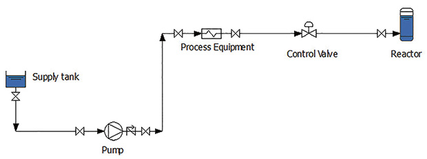 Figure 1. This single system is one of the many interrelated systems designed for the total process. (Graphics courtesy of the author)
Calculate the Static Head
In the example, the exact location of the supply tank and reactor have not yet been decided. The designers have an approximate size of the tank and vessel based on the process requirements. Until the civil department is able to complete the design of the tank foundations, the exact elevations and location of the supply tank and pressure vessel are estimated. The bottom of the supply tank is estimated to be at an elevation of 100 feet above sea level, but the bottom elevation of the tank could vary by plus or minus 10 feet. The estimated elevation of the nozzle into the reactor will be 180 feet above sea level, with a margin of plus or minus 10 feet. Using the estimated elevation of the tanks, the elevation head for this system could be as low as 60 feet (170 feet – 110 feet) or as high as 100 feet (190 feet – 90 feet). The preliminary design will use 100 feet. Last, the operational pressure in the reactor is specified at 10 pounds per square inch gauge (psig) including the static head, but the operational pressure could vary by plus or minus 2.5 pounds per square inch (psi) from the design pressure. This pressure variation creates an additional 6 feet of pressure head. The resulting static head used in the preliminary design is 106 feet.Determine the Dynamic Head
The next step is to determine the head loss in the pipeline as a function of the flow rate. This calculation incorporates the physical properties of the process fluid, the pipe material, the pipe length, and the valves and fittings. Figure 1 includes all the isolation and check valves in the system. The design features these items to allow for the isolation of equipment for safe operation and maintenance. Other items, such as elbows and pipe lengths, are not indicated in the piping schematic. This exact information is not available until well after the preliminary design’s completion. As a result, the pipe length and the number of fittings needed along with the design margin must be estimated. The pipe length between the pump discharge and process equipment is estimated at 150 feet, but a 50 foot margin is added. Further, a need for five elbows is estimated, with a margin of three more. The final step in pipe sizing is calculating the head loss for each pipeline. The head loss is a function of the density and viscosity of the process fluid and the pipe inside diameter and roughness. The value for the pipe roughness and inside diameter is used in the head loss calculation. This information is referenced in pipe size tables for the selected pipe material. When a pipeline is in service, it can corrode or foul over time. This results in an increase in pipe roughness and a reduction in the inside of the pipe diameter, leading to an increase in the pipeline’s head loss during operation. A design margin may be added for this unknown decrease as well. The dynamic head for the system is calculated by adding the head losses of the individual pipelines to arrive at a total value of dynamic head. A design margin is often added. The differential pressure for the process components must be factored into the pump sizing calculation. During the preliminary design, the process equipment has not been selected, so an estimated pressure drop must be used. The EPC has specification documents for the process equipment stating a maximum acceptable differential pressure in this system. For this equipment, the EPC allows a maximum of 15 psi. This estimate is converted to head and added to the dynamic head calculation for the process elements. The sum of the static and dynamic head values is the head required by the process elements. Often, additional design margins are added based on experience. For example, pipe roughness may increase because of corrosion, or the pipe inside diameter may decrease because of sedimentation. This adds to the head loss in a pipeline but is hard to quantify, so a design margin may be added to take into account these unknowns. The person performing the sizing calculations included these unknowns, but it was not documented. Because of this, another person added his/her own design margin for expected pipe corrosion. Additional design margins may be applied to the head loss during the review by the engineering manager. The last item to be sized is the control valve. The mechanical group may add a typical differential pressure value of 15 psi, which is converted to head and added to the total head value for the pump. With the results of the preliminary design complete, the EPC can develop a specification for the pump. The team specifies a flow of 800 gpm and a head of 211 feet of fluid.Select the Pump
Next, the specification document is sent to the supplier for pump selection. Sales engineers often recommend pumps that have a best efficiency point (BEP) to the right of the design flow rate because they want to make sure that the selected pump can continue to meet the end user’s needs as the system capacity increases over time.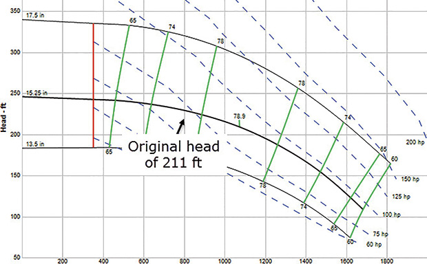 Figure 2. The pump curve selected for the application
Examine the System Curve
After the preliminary design is completed and the equipment requirements are determined and recommended, the EPC team can see how the entire system works together (see Figure 3).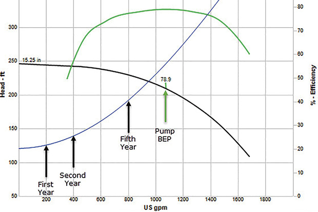 Figure 3. The pump system curve shows the interaction between the pump and the system, including the plant’s changing loads through the years.