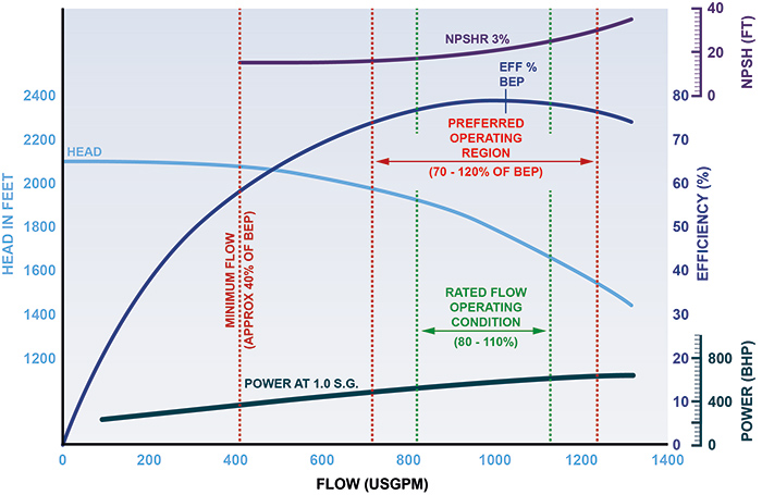
Centrifugal pumps make up nearly three quarters of the industrial pumps in use today and are commonly used in the power generation sector. An understanding of the design principles and an awareness of the latest developments can make a big difference when designing, specifying, maintaining or replacing a centrifugal pump in order to deliver long term reliability. As a vital piece of equipment within a power generation site, centrifugal pumps need to be correctly specified and maintained to deliver efficient and reliable service. This process of specification begins with understanding the basic terminology, principles and design characteristics to ensure that each pump can meet its full potential and deliver the required performance. Every pump has a performance graph that should be used to determine the suitability of the pump for a particular application. For a range of flows, the graph indicates the generated head, power requirement, efficiency and the net positive suction head required (NPSHr). Each pump design has an optimum flow rate, which occurs at the best efficiency point (BEP). In this example, the normal operation conditions (80 to 110 percent of BEP) and the preferred operating region (70 to 120 percent of BEP) are on either side of the BEP. Pump efficiency is a crucial factor when designing a pumping system, since 95 percent of the lifetime costs for a pump will be the energy it uses.
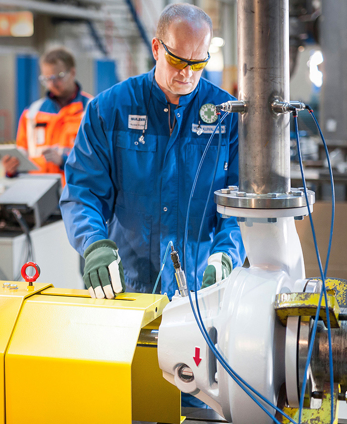
 Image 1.Expert assistance from original equipment manufacturers (OEMs) can reduce downtime. (Images and graphics courtesy of Sulzer Pumps)
 Figure 1. Pump performance graph
Parallel or Series Solutions
In some situations, the specification of a centrifugal pumping system will involve multiple pumps, either in parallel or series configurations. This enables a number of smaller pumps to deliver much greater flow or head, depending on the pump arrangement, which may be preferable to a much larger, single pump. Image 2. Extensive testing and refinement improves performance.
Understanding Specific Speeds
Modern pumps are classified by their specific speed, which is a dimensionless quantity that describes the geometry of the pump’s impeller. Specific speed is a correlation of pump capacity, head and speed at optimum efficiency, which classifies pump impellers with respect to their geometric similarity. The specific speed of an impeller is defined as the revolutions per minute (rpm) at which a geometrically similar impeller would run if it were of such a size as to discharge one gallon per minute (gpm) against one foot of head. Similarly, the suction specific speed is a rating number, which is also dimensionless, that indicates the relative ability of centrifugal pumps to operate under conditions of low net positive suction head available (NPSHa). Pumps with a low specific speed, 500 rpm for example, will have radial flow impellers that produce high head but lower flow rates. An axial flow impeller, with a specific speed of 10,000 rpm, will produce high flow rates and low heads, while a mixed flow impeller delivers a compromise between the two. Image 3. The design principles remain the same, regardless of scale.
