How to extend the life of second-stage impellers and eliminate inlet vane cracking.
Saudi Aramco
09/19/2019
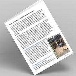
The pumps referred to in this article are two supply pumps with a flow of 36,500 gallons per minute (gpm), head at 2,200 feet and 27,000 horsepower (hp) that move seawater 200 kilometers (km) to be injected into an oil reservoir to maintain a high pressure. The suction line distributes flow to two first-stage impellers, which discharge to two second-stage impellers (Image 1).
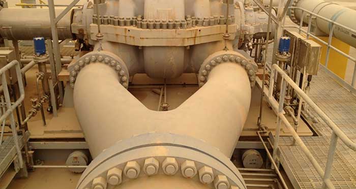 Image 1. Supply pumps field installation (Images courtesy of Saudi Aramco)
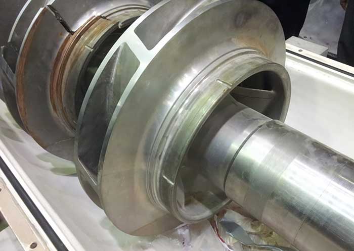 Image 2. NDE first- and second-stage impellers.
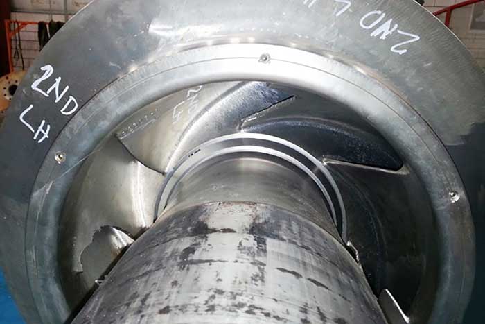 Image 3. Second pump NDE second-stage impeller.
Findings & Discussion
The laboratory report confirms that the second-stage impeller materials were in accordance with chemical and physical properties specified for the impeller. It indicated casting defects in a piece of vane as a “cold shut,” and suggested that defect may be a contributor to the failure (Image 4).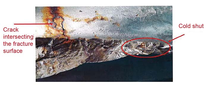 Image 4. Cracked surface of the impeller inlet vane.
 Image 5. Second-stage impeller with 0.005 inch interference fit
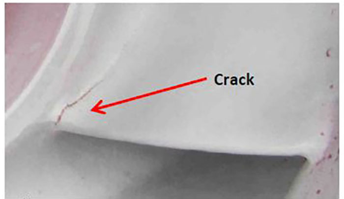 Image 6. Second-stage, leading edge crack (GT6001) dye penetrant inspection
- The impeller material was upgraded from austenitic stainless steel (ASTM A351 gr. CF3M) to super duplex stainless steel (ASTM A890 gr. 5A).
- The range of the interference fit between the impeller and shaft was reduced from the range of 0.003 to 0.005 inches to 0.001 to 0.003 inches.
- The wear rings were eliminated, and the wear surface on the impeller was overlaid with tungsten carbide, using the direct laser deposition process.