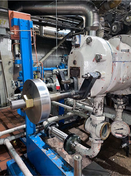
Pumps are critical components that can directly affect the safety, production capacity and revenue generation of industrial units. As such, it is essential they operate reliably and problematic behavior is understood and corrected. Sometimes problems that arise can be easily diagnosed and proven solutions implemented quickly to reduce risk to unit operation. Other times there is no single “smoking gun” that points to a well-defined root cause, and the process of diagnosis and resolution is less straightforward.
In aging installations, the second case is happening more frequently. Several industries are encountering plants that have aged significantly and are facing challenges inherent in older systems. The power industry notably has compounding layers of challenge, as the industry itself is shifting. Aging installations are faced with changes in demand, as output has changed from the original design based on consumers’ changing needs and efforts to reduce contributions of emissions-heavy facilities to the grid.
Plants that used to be base-loaded may now operate in a peaking capacity. Budget constraints for plants with uncertain futures have affected maintenance cycles, and equipment is being operated at a greater level of degradation and wear than previously encountered. All of these factors add up to a greater risk for complex problems in equipment that had previously operated reliably.
This was the situation a coal-fired power plant in the Midwest found itself in when its startup boiler feed unit (SUBF) began to exhibit high vibration that was not easily attributed to a distinct root cause. Plant personnel partnered with the field engineering division of an independent pump aftermarket service provider to engage in an in-depth study that would determine the causal factors of the vibration and develop a working solution. This study required several stages of testing and analysis to isolate the source of the vibration.
Initial Testing & First Impressions
The subject SUBF is an 8-stage barrel pump that had been recently rebuilt. Upon reinstallation, the site reported the pump was exhibiting high vibration at running speed (1X) that measured approximately 1.6 inches per second-root mean square (IPS-RMS). The pump tripped several times due to the elevated vibration and could not be brought online during unit startup. The element was removed and inspected for any issues by the facility that had completed the initial refurbishment and was judged to be in good condition, and residual imbalance met required specifications.
At this point, plant personnel contacted a different independent pump aftermarket provider who had previously performed complex troubleshooting on other applications through their field reliability engineering department. The first step the service provider’s reliability team took was to travel to the site to collect vibrational data during pump startup.
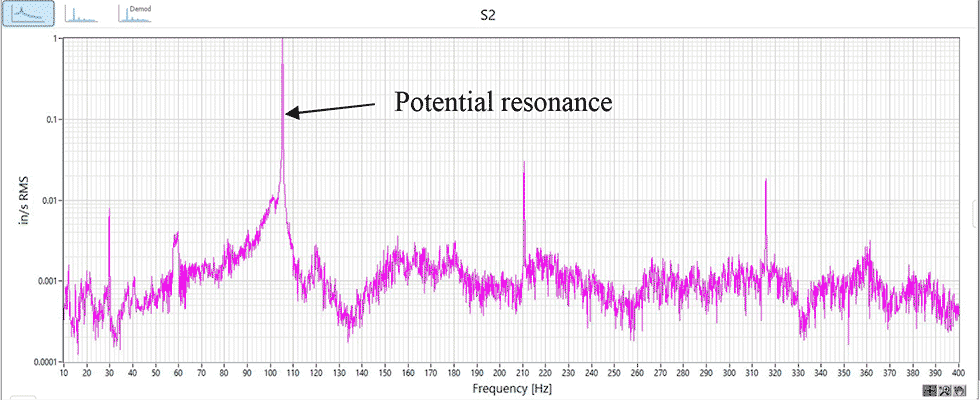
This testing verified there was a high 1X dominant forcing frequency occurring at the pump running speed of 6,300 rotations per minute (rpm) or 105 hertz (Hz). On-site testing revealed the highest 1X vibration was occurring at the outboard bearing housing in both the vertical and the horizontal direction.
While on-site, the team reviewed the unit history and discovered the drivetrain was recently equipped with a new coupling. Comparison of the new coupling with the original coupling revealed it was 60 pounds (lbs) heavier. Because the pump had operated without elevated vibration with the original coupling installed, the reliability team suspected this was an important factor in the current vibration levels.
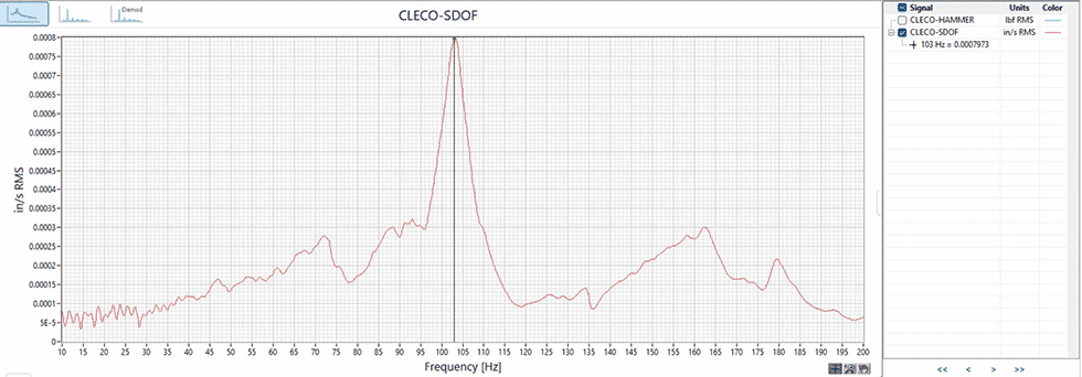
When looking at the vibration spectra, it was determined that the 1X peak indicated a potential resonance (Image 1). This was especially evident when looking at the logarithmic spectra, which showed the classic inverted V-pattern associated with resonance. The reliability team performed a bump test on the outboard bearing housing to identify the natural frequency of that component and determined the margin between this frequency and the forcing frequency at 1X. This test revealed that the natural frequency of the outboard bearing housing was 103 Hz, which provided very little margin and made excitation of a structural resonance likely (Image 2).
At the end of the initial testing, the reliability team was confident the unit was facing a resonant condition. What was still undetermined was whether this resonance was structural, rotating or a mix of both. Evidence from the bearing housing bump test and coupling change showed either was a distinct possibility. The next step in the troubleshooting plan was to make changes that would validate or refute the structural resonance of the bearing housing to get a clearer picture of what was occurring.
Detuning the Structural Resonance
In order to reduce vibration associated with the suspected structural resonance, the reliability team designed a dynamic vibration absorber (DVA) to detune the 105 Hz 1X frequency. A DVA works by having an identical natural frequency as the system to which it is mounted but vibrates in an opposing phase.
This opposing motion cancels out the resonant amplification. The DVAs designed for this unit were installed on both the inboard and outboard bearing housings.

After the DVAs were installed, the reliability team performed another round of in-depth field testing. The testing revealed a reduction in vibration in the vertical direction, but the levels were not reduced enough to be considered acceptable. Vibration in the horizontal direction was sensitive to the DVA but could not be tuned enough to provide a significant reduction. The inability to tune the DVA was attributed to both time constraints and the high level of excitation force energy.
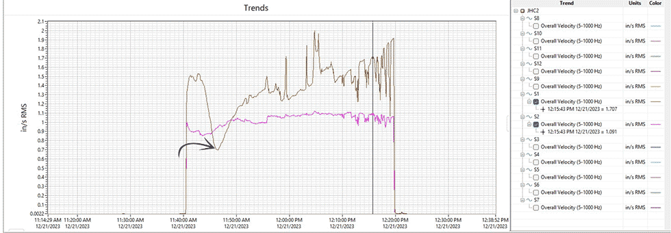
One additional observation was made during this round of vibration testing. Horizontal vibration dropped significantly during the test at a time that coincided with high pressure in the seal water supply (Image 4). This observation further validated the need for a rotor analysis to understand the margin between the rotor critical speed and the operating speed.
Lateral Rotordynamic Analysis
The next step in the root cause determination was to evaluate if the rotor was running near its critical speed and, if so, how to increase that margin. A simplified dry rotor analysis, which includes all masses without liquid, was performed to evaluate the critical speeds of the rotor. Results of this analysis indicated a possible critical speed too close to the 105 Hz operating speed. Following this result, a more complex lateral study was completed that took into consideration the effect of water passing through close clearance areas. As originally suspected, this study showed that the new coupling installed resulted in a critical speed within the amplification zone.
To increase the margin between the critical speed and the operating speed to an acceptable level, the aftermarket service provider proposed modifying the current coupling to use titanium components.
This material change would reduce the weight and inertia of the coupling to move the critical speed outside of the amplification zone. A target of 20% was set based on API 610, which is more conservative than other standards, such as API 672, which allows a narrower margin of 16%.
The wet rotordynamic analysis was completed for both design clearances and worn clearances. The analysis took into consideration how four different coupling designs would affect the critical speed of the rotor and the margin to the operating speed:
Scenario 1: existing rotor with current coupling, no changes
Scenario 2: existing rotor with current coupling modified for titanium hubs
Scenario 3: existing rotor with current coupling manufactured completely from titanium (excluding disk pack)
Scenario 4: existing rotor with new coupling
The analysis demonstrated that scenarios 3 and 4 both brought the separation margin within an acceptable level. While scenario 2 improved the margin, at 14% it was still below the level deemed acceptable by the team. Lead time to procure a new coupling and indications within the analysis that scenario 3 would yield a slightly better response led to the decision to completely remanufacture the existing coupling design from titanium. This solution would result in a minimum separation margin of 19.66% even with clearances worn to two times the design value.
Installation of the modified coupling was accompanied by another round of on-site testing to validate the efficacy of the change. It was determined the DVAs would remain installed on the outboard end of the pump and be finetuned during testing to reduce the vibration related to the suspected outboard bearing housing structural resonance.
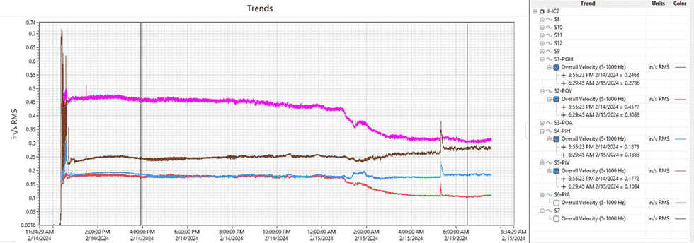
Initial startup of the unit resulted in a much lower vibration at 0.457 IPS-RMS. This vibration was further reduced to 0.305 IPS-RMS after 18 hours of operation (Image 5).
By combining historical data, engineering experience and comprehensive field testing, the power plant and aftermarket service provider were able to successfully diagnose a complex vibration issue and develop a clear path to viable operation. Being able to understand the nature of the resonances being excited and the factors that influenced their sudden appearance eliminated the need for costly trial and error.
The coupling modification and DVA installation were able to reduce pump vibration to a level that returned the unit
to reliable operation. Armed with the data collected during the causal analysis and solution development, the site can make informed decisions about future actions, such as an operating deflection shape (ODS) study, to further reduce vibration.

