In my previous column, a plant engineer used a piping system model to determine why the facility’s large cooling water system was not operating properly. After building the piping system model to reflect the design of the installed piping system, the engineer discovered the installed system was not operating as described in the physical model. This situation made the plant engineer question why the physical piping system was not operating as the piping system model. As stated in the article, the problem was that the throttle valves were fully open in all flow circuits. This resulted in a flow rate through the entire system that exceeded the capacity of two cooling water pumps operating in parallel. As a result, the plant had to operate three pumps in parallel. Rather than continue to run three pumps in parallel with higher flow rates through each circuit, the plant engineer decided to balance the system by positioning the throttle valve to achieve the design flow rate through each circuit. Reviewing the system’s operation after balancing, the engineer discovered that two circuits within the system did not have sufficient flow rates to maintain the outlet temperature of the cooling load. The immediate objective was to operate the plant to meet the production requirements, so the flow rate through the two problem circuits was increased.
Troubleshooting Heat Exchangers
The plant engineer was not completely satisfied with the result of increasing the flow rate through the two problem circuits. He questioned why the two circuits could not maintain the outlet temperature with the design flow rate. Two possible reasons for the difference arose:- There were problems in the heat exchangers in the two circuits that were not operating as designed.
- The established engineering principles of heat transfer for some reason did not apply to these two heat exchangers within this particular system.
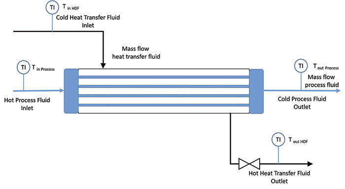
 Figure 1. Schematic of a typical heat exchanger, showing how thermal energy is exchanged between the process fluid and the heat transfer fluid. The objective of the cooling circuit is to limit the flow rate of the heat transfer fluid to maintain the outlet of the process fluid to the required value. (Courtesy of the author)


