Pumps & Systems, July 2013
Second of Three Parts
The secondary configurations reviewed in Part One (Pumps & Systems, June 2013, read it here) are typical three-phase configurations found in pump applications. However, several Delta mutants can be problematic and will almost always result in reduced motor life.
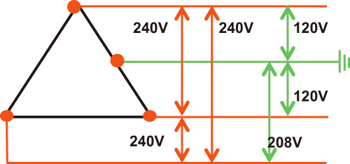
Center-Tapped Delta
A mutant that is becoming more common is the Center-Tapped Delta. As seen in Figure 1, this configuration attaches a grounded neutral to the center of one of the phase windings. The phases on either side of the center tap provide 120-volts single phase. However, the phase on the opposite side produces 208 volts. If you accidentally connect a control circuit to this leg, expect to see some smoke!
Unlike the Wye secondary, only two connections are available for single-phase loads. If too many loads are connected to one or both of these connections, voltage unbalance can occur in the three-phase circuit.
These transformers will provide balanced power as long as they are sized properly and single-phase loads are accounted for during sizing.

Figure 1. Center-Tapped Delta
Open Delta Secondary
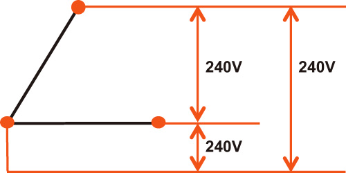
Figure 2 is an Open Delta secondary. Open Delta systems employ two, single-phase transformers to produce three-phase power but provide only 58 percent of the power produced by three, single-phase transformers. They are used by the electric utility when only two phases are available and are often seen in rural areas.
Although the phase-to-phase voltage is the same as the standard Delta, these systems are prone to unbalanced voltage among the phases. A small voltage unbalance of only 2 percent can result in a current unbalance of 12 to 16 percent.
When the voltage supplying a motor phase winding is reduced, current and temperature will increase. The result is reduced insulation life.
A variable frequency drive (VFD) can be used to balance the voltage in installations that are prone to unbalance, but the drive must be sized to accommodate the increased current. A DC choke may also be required to mitigate any harmonics that may arise because of the unbalanced impedance of the phase windings.

Figure 2. Open Delta mutant
Center-Tapped, Open Delta
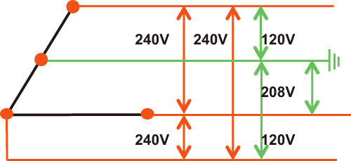
The worst-case example of mutant Delta transformers is the Center-Tapped, Open Delta shown in Figure 3. This design combines all the weaknesses of the previous mutants. Center-Tapped, Open Delta systems are subject to voltage unbalance because only two transformers are used.
This system also increases the probability of unbalance by providing two, single-phase connections on a single transformer.
If this design powers a three-phase motor and its single phase control circuit, it is always best to disconnect all other single-phase loads.

Figure 3. Center-Tapped, Open Delta mutant
Mutant Delta Use
When using these mutants for three-phase pumps, end users should be cautious. Measure and calculate the Open Delta voltage unbalance frequently and consider installing a VFD if the unbalance is more than 1 percent in the three-phase circuit.
Make sure that the single-phase loads are balanced on the Center-Tapped Delta and that unbalance in the three-phase connection is 1 percent or less.
If possible, avoid single-phase loads on Center-Tapped, Open Delta transformers if the three-phase load is 75 percent or more of the total capacity. If the two transformers are different sizes, the larger one should contain the center tap. Read the next part of the series here.

