As weather-related events continue to increase and reach catastrophic levels in coastal areas, drinking water and wastewater infrastructure systems are taking on more risk of flood-related damage. These systems are critical to society and the health of our environment. It is vital that infrastructure systems can withstand natural disasters while providing the ability to respond to these challenges and aid in recovery.1
A main strategy in reducing risk in these systems is the use of equipment that will operate while underwater, for as long as necessary. When water and wastewater plant operators are looking to “future-proof” their systems to be more resilient in the face of natural disasters, continuous underwater electric actuators can provide needed peace of mind.2 If high waters are a permanent risk, continuously submersible actuators offer a reliable solution even when flooding conditions persist, such as in areas prone to monsoons or hurricanes.
Hydroelectric power applications can also take advantage of underwater electric actuators in a variety of duties, whether it is diverting the flow of water via guide vanes, controlling flow through the turbine or in a variety of other ways.3 When used in water treatment or wastewater plant applications, explosion-proof versions of underwater actuators can be used in potentially explosive environments such as sewage treatment plants, sewage channels or pits, where fermentation gases like methane are present.
Defining Underwater in Electric Actuators
One can explore the diverse meanings of “underwater” in electric valve actuation by referring to various standards for clarification. Both the National Electrical Manufacturers Association (NEMA) and the International Electrotechnical Commission (IEC) have developed ratings to grade the resistance of an enclosure against the intrusion of liquids.
NEMA defines Type 6P enclosures as being able to “provide a degree of protection with respect to harmful effects on the equipment due to the ingress of water (hose-directed water and the entry of water during prolonged submersion at a limited depth).” Similarly, IEC developed the Ingress Protection (IP) rating system where IPx8 rated enclosures are subjected to immersion in water to a defined depth greater than 1 meter (m) and duration greater than 30 minutes.
Although NEMA and IEC use similar definitions, there are occasions when these standards do not offer a true indication of if an electric actuator is designed for continuous operation or a defined duration due to a temporary flood event. The electric actuators that are designed for continuous underwater operation are tested to perform at depths up to 197 feet (ft) (60 m) for more than 96 hours.
Aside from the immersion aspect, any equipment submerged continuously is subject to corrosion. In these demanding applications, submerged electric actuators require specific corrosion protection to ward off the effects of high salinity in marine, coastal and offshore areas, fresh or sea water, brackish water, soil and areas of high pollution.
Sealing is of the utmost importance to make sure the electric actuator is not compromised by the external fluid it is submerged in. Additional features a designer should look for in these types of actuators are:
Non-intrusive controls: Digital controls can utilize fieldbus communications and provide actuator performance analytics. They provide the ability to control and monitor the actuator while it is submerged, making commissioning the system easier.
Solid stainless steel shaft for valve actuation: This minimizes the chance for corrosion of the drive shaft that transmits critical torque to the valve.
Double seals on bearings, frame and cable glands: These are used to seal the internal actuator components from ingress of water that can cause damage to electrical components.
Remote mounted local controls:
These connect via an umbilical cord and provide the flexibility to locate the user interface virtually anywhere outside the flooded area for direct actuator operation.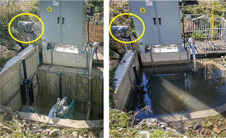
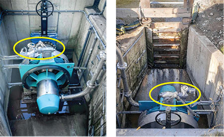
IMAGE 2: Turbine pit before and after commissioning. Remote mounted controls (rear left), mounted above the shaft and separately from the actuator, provide the ability to operate the underwater actuator for turbine guide vane control. Benefits of an Underwater Actuator for Continuous Use
When choosing a solution for an underwater actuator for continuous use, there are two main choices: hydraulic-powered actuators and electric-powered actuators.
Ease of installation: To start, electric actuators are easier to install. Power and signal cables need only be run from the actuator to the control box mounted remotely above the flooded area. All components required for operation of the actuator are contained within the actuator housing. Waterproof conduit entries are needed to ensure the actuator enclosure is leak-free from the beginning.
More environmentally friendly: In contrast to hydraulic-powered actuators, electric actuators are well-suited for applications where environmental regulations restrict the use of hydraulic liquids, even if they are biodegradable hydraulic oils. Continuously submersible actuators use no hydraulic fluid that can leak into the surrounding environment and cause contamination. Electric actuators do not use hoses, tubing or fittings in their operation that contain joints or potential leak points for working fluid to escape.
Reduced maintenance: Electric actuators also require less maintenance for operation than their hydraulic or wet pneumatic counterparts. The actuators and accompanying gearboxes are designed for continuous use underwater, with only periodic checks required to confirm proper operation a few years after installation. They do not require maintenance of pumps, hydraulic tubes, control valves or liquid reservoirs. Furthermore, hydraulic actuators must be maintained and serviced throughout the complete system lifetime while access to components is often quite difficult.
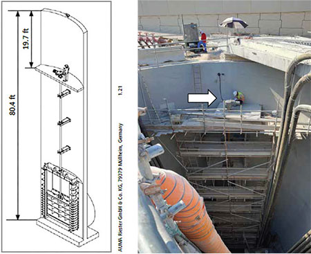
IMAGE 3: Stormwater chamber section 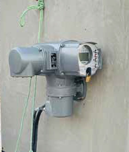
IMAGE 4: Actuator controls mounted remotely Case Studies
Application: Hydropower Turbine Control
Challenge:
A California-based turbine manufacturer required an actuator that could operate continuously underwater, provide accurate positioning to optimally control the water supply to the submersible hydro turbine and send feedback signals to the higher-level programmable logic controller (PLC). Previously, their only option was a hydraulic actuator.
Solution:
The user chose an electric actuation solution that provided better control and feedback at a much lower total cost. The actuator for continuous underwater use proved to be ideal for this application. The actuator’s high positioning accuracy (≤0.2 %) with continuous feedback was controlled by the PLC. The ability to mount the actuator controls separately allowed the end user to operate the actuator locally should the PLC fail. Due to the low power consumption of the variable speed actuator, the end user was able to utilize an uninterruptible power supply (UPS) as a backup in case main power was lost.
Application: Stormwater Management
Challenge:
While upgrading the stormwater network of E Ring Road in Doha, Qatar, the user needed a solution to ensure roller gates in the underground concrete chambers could operate and shut off DN 2700 stormwater pipelines in case of emergency. The actuators chosen to operate the huge 8.8 ft (2.7 m) roller gates had to be installed inside the chambers. With a total chamber height of 80.4 ft (24.5 m), the actuators had to be mounted approximately 19.7 ft (6 m) below ground level. The user looked for something that could be submerged in water for extended periods of time due to the likelihood of flooding during heavy rainfall.
Solution:
The user selected powerful underwater actuators that were designed for continuous underwater use at up to 49.2 ft (15 m) head of water. While each actuator was mounted on an access platform inside the chamber (Image 3), the non-intrusive actuator controls were mounted separately from the actuator outside the floodable area using a wall bracket. All local operation could therefore be done safely from a comfortable position using the remote mounted actuator controls.
As environmental threats of flooding events become more of a concern for water management projects, systems designers need to consider the benefits of electric actuators for continuous underwater service. These actuators prove to be a viable solution to solve a variety of scenarios. Electric actuators used in these situations offer easier installation and reduced maintenance and are more environmentally friendly than non-electric alternatives.
References
Apurva Pamidimukkala, Sharareh Kermanshachi*, Nikhitha Adepu and Elnaz Safapour. Resilience in Water Infrastructures: A Review of Challenges and Adoption Strategies. Sustainability 2021, 13, 12986. oi.org/10.3390/su132312986
Butler, D.; Ward, S.; Sweetapple, C.; Astaraie-Imani, M.; Diao, K.; Farmani, R.; Fu, G. Reliable, resilient and sustainable water management: The Safe & SuRe approach. Glob. Chall. 2016, 1, 63–77. [CrossRef]
Schmeding, Heike, Underwater electric valve actuators for Voith hydropower plant – A case study, Actuation, July 2017, 54-55.