
How electronic speed control drives, adjustable frequency drives, magnetic drives and steam turbine drives work to achieve true variable speed control.
06/26/2019
Editor’s Note: This is part 2 of 2 in a series. Read part 1 here.
In a February 2019 Pumps & Systems article, we reviewed how, over the years, the pump industry has been introduced to more advanced and versatile methods to control pump speed.
To achieve true variable speed control, we are looking at the following methods or technologies: fluid drive, eddy current drive, wound rotor motor, adjustable voltage direct current (DC), adjustable frequency alternating current (AC), magnetic drive and steam turbine. Part 1 of this series reviewed fluid drive, eddy current drive and wound rotor motor. This article will review the other methods or technologies.
Electronic Speed Control Drives: Adjustable Voltage DC
The oldest electronic speed control methods are the DC drives, which are also known as DC motor speed control systems. The speed of a DC motor is directly proportional to armature voltage and inversely proportional to motor flux; either armature voltage or field current can be used to control the motor speed. DC motors have become expensive and most DC motor speed control systems have been retrofitted with an AC motor and AC variable speed drive. AC variable speed drives are less expensive, more available and more efficient than DC systems. Many DC drive systems have been replaced where possible with AC variable frequency drives (VFDs).Adjustable Frequency Drives
A VFD is the most popular method to control the speed of an electric motor driven pumping system.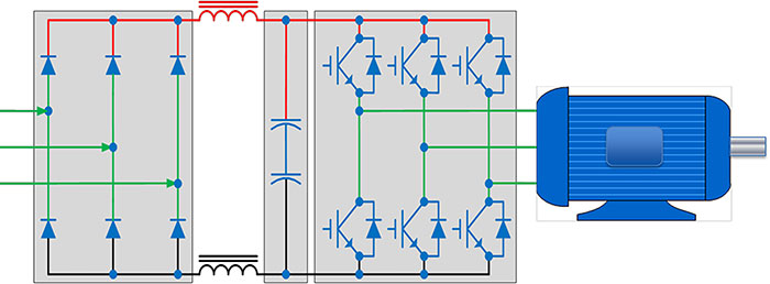 Image 1. Basic drive system (Images courtesy of the author)
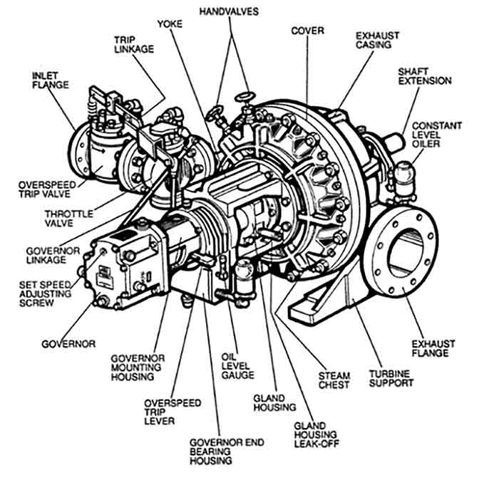 Image 2. Components of a typical steam turbine driver
Maintenance
The VFD must be in a clean, filtered environment. Heat the sinks, vacuum away dust and do not use compressed air. If heavily soiled, used a light natural fiber brush. Do not use a synthetic brush. For Type 12 enclosures with cooling fans, replace the air filters as necessary. Conduct a thermal scan, paying special attention to the connections. Check the cable lug torque. Use a megger to measure insulation resistance. The typical life expectancy of a VFD is five to 10 years. After 10 years, most drive OEMs will discontinue the manufacturer or replacement parts. In addition, VFD technology continues to change, making older drives obsolete.Magnetic Drive
The principle behind a magnetic drive or coupling is like that of an eddy current drive. The magnetic drive replaces the physical connection between motor and load with a gap of air. Motor torque is transferred to the load across an air gap. Varying the air gap between the magnets and conductor changes the strength of the magnetic field and, hence, controls output speed. A few features of magnetic drive technology:- No-contact power transfer. This eliminates vibration, reduces noise, tolerates misalignment, provides overload protection, extends motor and equipment life and reduces overall maintenance costs.
- Energy efficiency. The application and load requirements will determine the efficiency.
- Quality. Technology improves product quality and optimizes process rates.
- Soft start/stop. Reduces the motor’s startup power demands and the resulting brownouts, alleviates paying for peak power, allows downsizing of motors, increases motor life and reduces maintenance.
- Simplicity and ruggedness. System can be maintained in-house and used in harsh conditions.
Steam Turbine Drive
Steam power is one of the oldest technologies in the industrial sector providing power through the industrial revolution and into the 20th century. However, there are some limitations when applying a steam turbine. First and foremost, you need steam and you need a source to generate the steam. This requirement limits the use of turbines in certain applications. The most notable pumping application for steam turbine drivers is powering boiler feed pumps. A steam turbine is powered by the hot gaseous steam generated by a boiler. The steam enters the turbine through a nozzle that controls the speed of the steam (Image 2). The turbine is fitted with blades mounted on a shaft that is coupled to the driven component (pump) that turn as the steam blows past them. The blades have tight clearances that contain the steam, maximizing the efficiency of the turbine. The steam expands and cools as it flows through the turbine blades.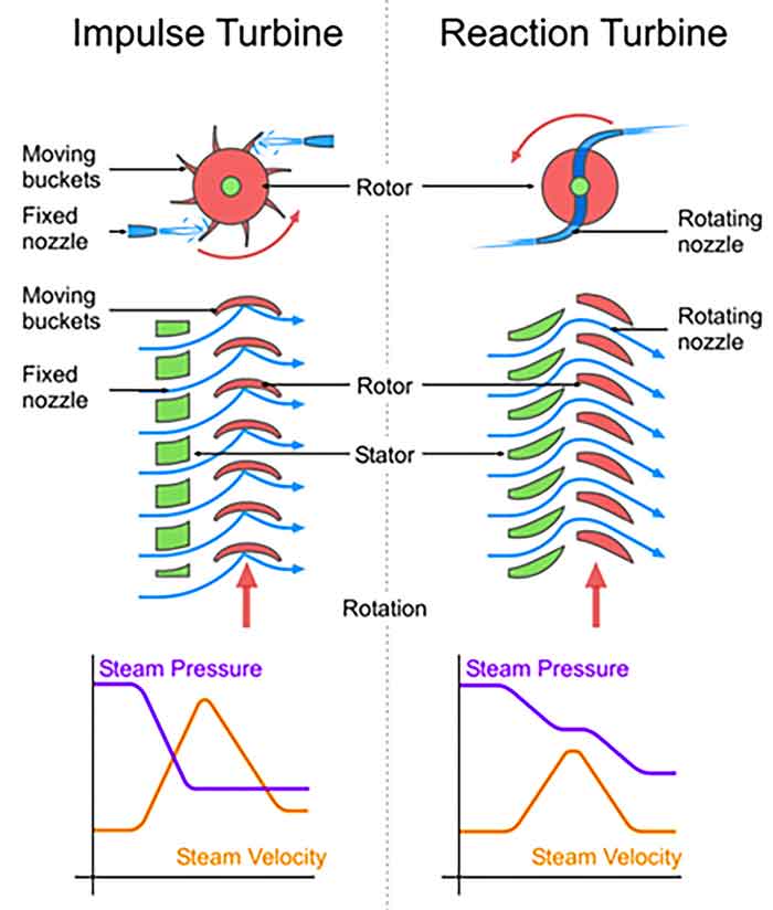 Image 3. How an impulse turbine works vs. a reaction turbine
- An impulse steam turbine features a jet of steam from a fixed nozzle that pushes against the rotor blades driving the blades forward (Image 3). Pressure drops take place in the fixed blade (nozzle).
- A reaction steam turbine does not use nozzles. The rotor blades are configured to form convergent nozzles using the reaction force produced as the steam accelerates through the nozzles. The steam is directed onto the rotor by the fixed vanes in the stator (casing).
