System Head & the Operating Point
The pump operating point is a function of the system requirements. Simply put, the system flow rate will be the flow rate where the pump curve and system curve intersect. Image 1 illustrates a pump head versus flow rate curve (pump curve) and the system head versus flow rate curve (system curve). The blue dot marks the intersecting point or the flow rate and head the pump will operate.
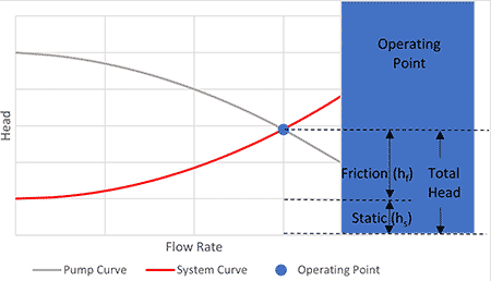
The system curve consists of static head and frictional head loss. Static head represents the height the liquid must be lifted plus the pressure head difference acting upon the liquid. This is referred to as static head because the pump flow rate does not have a direct correlation to it increasing or decreasing. Frictional head loss is the hydraulic energy required to overcome frictional resistance to liquid flow of a piping system. As stated in this definition, the friction head has a direct relationship to flow rate or the liquid velocity in the piping system, which is the focus of this article.
Frictional Head Loss
It is important to consider the frictional head loss in a pump system because it is a major contributor to the amount of energy consumed by the system and the size of the pump required to deliver the rated flow rate. The head loss due to friction can be calculated based on the velocity through the system components, such as piping, valves, elbows and bends. These losses typically vary proportionally to the square of velocity. As such, limiting the velocity is key in reducing the system frictional head loss and the system energy requirements. The losses calculated for the flow through system piping are referred to as major losses, and losses through valves, elbows and other fittings are referred to as minor losses.
Pump & System Resources: Engineering Data Library
The piping (major) losses can be calculated with the Darcy-Weisbach friction factor, the pipe length, the pipe inside diameter and the liquid velocity through the pipe. The friction factor is determined from the Reynolds number and the relative roughness of the pipe. The fitting (minor) losses are calculated based on the flow coefficient (K) and the velocity head. The K for fittings and valves is developed based on testing and is published as typical values in engineering reference manuals.
The Hydraulic Institute recently published Phase 2 of its free pump and system resource website, the Engineering Data Library (edl.pumps.org), which provides pump and system fundamental information, instructional demonstrators, tools and calculators useful for the pump and fluid handling industry. Section III A and B of the site provide specific details on how to calculate frictional head losses in pipe and fittings, but to make it easier for the user, one of the tools included in the site is a pipe frictional loss calculator. This calculation tool removes the manual lookups and hand calculations and completes the described calculations by gathering pipe dimensions from industry standards and industry-accepted equations published on the site.
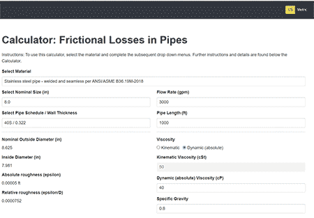
Image 2 shows the inputs for the pipe frictional head loss calculator. Units can be toggled between United States and metric at the top right of the tool. Following selection of the desired units, the user can select the pipe material, nominal pipe size and rating from a list of standards that include steel, stainless steel, ductile iron, nonferrous and polyvinyl chloride (PVC) pipe materials. These selections inform the pipe inside diameter and relative roughness, which is needed to determine the friction factor used in the calculation. The user then inputs the flow rate, length of pipe and liquid viscosity, which allows the Reynolds number to be calculated and the friction factor determined.
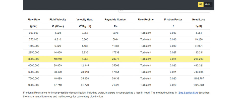
The output of the calculator is shown in Image 3. Calculations for the user input flow rate of 3,000 gallons per minute (gpm) are highlighted in yellow, but it also shows calculations for a range of flow rates above and below the user input flow rate. Calculations displayed are the fluid velocity, velocity head, Reynolds number, flow regime, friction factor and head loss. In this example, the frictional head loss is 216 feet (ft) for the inputs shown in Image 2.
Considering Energy Savings
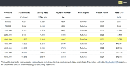
If desired, the user can then quickly compare the frictional head loss for a different pipe size. Image 4 shows the calculator output for a 10-inch nominal pipe of the same schedule, keeping all other inputs the same. Moving from an 8-inch nominal pipe to a 10-inch nominal pipe decreases the fluid velocity from 19.2 feet per second (ft/s) to 12.2 ft/s, which results in the frictional head loss decreasing from 216 ft to 73 ft. At 3,000 gpm, the 73 ft reduction in head loss corresponds to about 65 kilowatts of power savings. For a system operating continuously and with a cost of electricity of $0.15 per kilowatt-hour, this equates to approximately $85,000 annual energy savings for the 10-inch pipe system, which the designer can consider in the life cycle cost consideration.
For more information on the calculation of frictional head loss and to explore additional free tools for unit conversions, line shaft bearing losses, tank volume calculations, atmospheric pressure based on height above sea level and motor dimensions, visit edl.pumps.org.