How do end users choose, and what are each type’s ideal applications?

Motor manufacturers routinely answer questions about the differences between submersible and immersible motors and the applications best served by each design. While end users ultimately decide which motor best fits their need, this article explains how the designs differ and provides information that will help end users make informed decisions.

Submersible Motors

Municipal and industrial wastewater markets use submersible motors for both wet and dry pit applications. These are totally enclosed, non-ventilated (TENV) motors. Wet pit motors use the effluent for cooling and are designed to run continuously while submerged. These standard designs are also rated to run in air for 15 minutes when conditions require it. These motors can also be designed for continuous operation in dry pit applications by de-rating a larger horsepower motor frame. This allows the motor to dissipate heat while running continuously in a dry pit application that only experiences flooding under unusual conditions, such as heavy rains or a backup in the system.
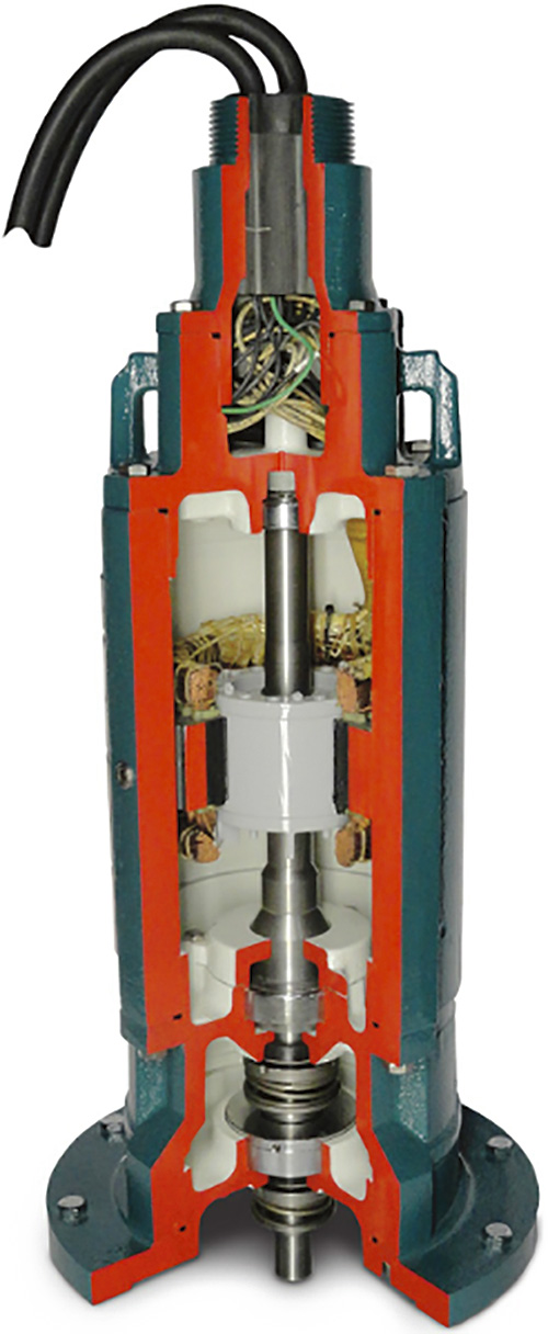
Submersible motor cutawayMany submerged motors rely on the effluent to stay cool and run continuously while submerged. (Article images courtesy of Baldor Electric Company.)
Submersible motors are rugged and corrosion resistant, making them suitable for demanding applications. The motors have cast iron frames and end plates. Most motors come standard with 316 stainless steel hardware and 416 stainless steel shaft material. Submersible designs are available for hazardous and nonhazardous locations. An example of a hazardous location is a sewage application where flammable gases might be present. These locations require an explosion-proof motor design. Explosion-proof motors are UL (Underwriters Laboratories) listed and CSA (Canadian Standards Association) certified for Division 1, Class 1, Groups C and D with a 1.0 Service Factor and T2A temperature code. Submersible motors use cast iron frames that are precision machined for tight fits between the parts. Machined fits have grooves with O-rings to prevent water ingress to the motor. An epoxy filled, non-wicking cable cap assembly protects the motor from moisture that could enter through the opposite drive end of the motor. Typically, two separate cables exit the cable cap epoxy potting compound; a four conductor power cable and a five conductor control cable. Standard lengths vary from 25 to 30 feet, but other lengths are available upon request. This cable should never be used to lift the motor. The drive end of submersible motors is a critical part of the design. Since the motors are designed to run continuously while submerged in water or effluent, they include features to keep water out. An oil filled chamber and a mechanical seal serve this function. Also, a moisture monitoring probe is used to detect moisture entering the chamber. The drive endplate has a special design that includes a chamber filled with oil. The oil acts as a barrier to trap moisture and provide sufficient time for shut down if water enters the motor. It also lubricates the upper part of the mechanical seal. The mechanical seal keeps moisture out of the motor. Some companies use a Type 21 mechanical seal as its standard submersible motor seal. This seal uses an inner and outer seal arrangement. It has both a stationary face and a rotating face. As previously stated, the upper part of the mechanical seal is lubricated by the oil in the endplate chamber. However, the lower part is lubricated by the pumped liquid. Carbon ceramic is the standard seal face mat­erial and is used in applications with relatively clean effluent. Tungsten carbide, which is used with more viscous fluids, is the most popular seal face material. For the most demanding slurry type applications, seal faces with tungsten carbide are an option. Pump manufacturers specify what type seal is necessary. Moisture probes are necessary because seals wear, and the potential for moisture to enter the motor increases over time. This sensing system, consisting of two probes with a resistor between them, is placed in the oil inside the endplate. The probes are connected to a customer-supplied control module that sounds a warning alarm or shuts down the motor if a change in resistance is detected. This ensures that the motor is shut down before any damage occurs. Worn seals will need to be replaced. This motor configuration is predominantly used for applications in which the motor will be submerged at all times.

Immersible Motors

Immersible motors, on the other hand, are specifically designed to be operated in a dry environment that might flood under unusual circumstances. One company’s immersible design was developed for an end user who needed a more cost effective alternative to the more expensive, oversized submersible frame motors used for continuous in air operation. Immersible designs use TENV enclosures in smaller frames and totally enclosed blower cooled (TEBC) enclosures on larger frames. They have a sealing system that allows reliable operation for two weeks while submerged under a maximum depth of 30 feet of water. The immersible design has been proven with extensive tests, including disassembly and inspection to ensure dryness and structural integrity. The TEBC design runs continuously in air and has a separate 1/2 horsepower motor running an external fan for constant velocity cooling. An end user-supplied float switch turns off the blower motor if the water reaches a level near the cooling fan. The opposite drive end is totally enclosed, and the fan and blower motor are mounted separately to ensure that moisture will not enter the motor from the opposite drive end. These motors are also built with precision machined cast iron frames and endplates with grooves and O-rings to prevent water ingress to the motor.
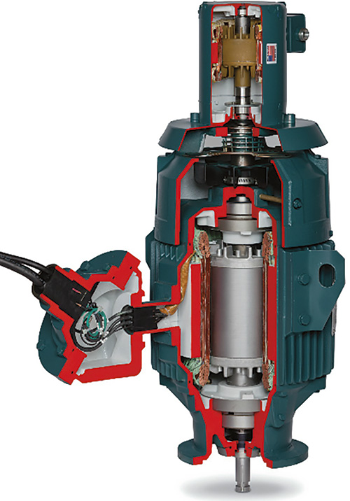
Immersible motor cutawayImmersible motors are specifically designed to be operated in a dry environment that might flood under unusual circumstances.
The drive endplate is designed to keep moisture out by using a dual oil seal configuration that is packed with heavy, moisture resistant grease. This endplate does not have an oil chamber like the submersible design. Another mechanical feature of the immersible design is an explosion-proof style conduit box that uses a sealing compound and a non-wicking epoxy-sealed cable assembly to prevent water from entering through the electrical connection at the motor. These motors use the same power and control cable configuration as the submersible motor design. Other standard features include: two normally closed thermostats, motor space heaters and a regreasable lubrication system. Lastly, the immersible design has the benefit of reducing costs over the traditional immersible pump configuration, which uses a non-immersible vertical pump motor mounted more than 20 feet above the pump and employs a jack shaft to reach it. The immersible motor mounts directly to the pump. This configuration eliminates the construction and installation costs incurred by building a motor support structure.

Conclusion

Application conditions should be the deciding factor between immersible and submersible motors. Immersible designs are more cost effective, but the submersible design is a better fit in an application that requires continual submergence.