Several new sections have been added.
W.L. Gore & Associates

The Fluid Sealing Association (FSA) has released the fourth edition of the “Compression Packing Technical Manual.” This update represents a four-year intensive joint effort of FSA and European Sealing Association’s (ESA) compression packing technical committee’s new technical learnings. These learnings can help inform end users on industry best practices and performance characteristics of compression packings.
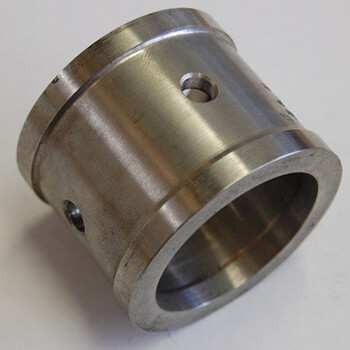
Lantern ringImage 1. Lantern ring (Images courtesy of FSA)
New sections to the manual have been added, including:
  • environmental controls
  • compression packing vs. mechanical seals
  • leakage rates
  • pump packing power consumption
  • determining stuffing box dimensions

Lantern Rings

A lantern ring is used to supply or extract different media to or from the stuffing box (Image 1). It has a number of holes and is located under a bore in the stuffing box housing for external injection or extraction of media. It can be made from metals like stainless steel, carbon steel or bronze or from plastic materials like polytetrafluoroethylene (PTFE), PTFE/carbon and others. Often, the lantern ring is used to supply a water flush for cooling the stuffing box or to apply grease for additional lubrication. Depending on the application and type of media, the location of the lantern ring and its function in the stuffing box may vary. In Image 2, different examples are shown.
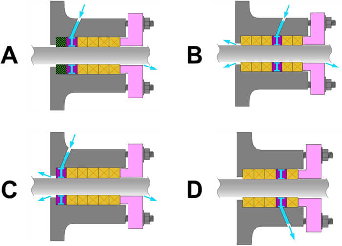
Lantern ring arrangementsImage 2. Lantern ring arrangements
In the case of hard and abrasive media like slurry or river water in Example A, a spacer ring may be installed at the bottom of the housing to reduce the clearances and to prevent larger solids from entering the stuffing box. The lantern ring is placed directly behind the spacer and flush water can be applied as a barrier fluid. Example B shows the configuration for crystallizing media such as sugar, paint or plastics. Here, the first three packing rings seal against the media and the flushing medium provides a barrier against the crystallizing fluid. The two packing rings on the gland side act as a secondary seal to minimize leakage from the flushing medium. In Example C, the lantern ring is placed directly at the bottom of the stuffing box to flush with an inert gas, which acts as a barrier against potentially explosive or toxic media. The following packing rings act as a safety seal. In Example D, the lantern ring is used for leakage extraction in case of special or expensive media, which can be redirected into the production process.

Packing Sealing Solutions Power

It has been assumed that pump packing friction and resulting power consumption is significant. In particular, it has been assumed to be significantly more than the power consumption of mechanical seals under similar pressure, size and speed conditions. An exhaustive study commissioned by the FSA and the ESA together with an extensive testing program completed by the Technical Centre for Mechanical Industry (CETIM) were conducted to verify this assumption, and it has proven that this was not accurate. The traditional theoretical power consumption of compression packings was given as: Equation 1: P = Pp x RPM x D x μ x Ap x F Where: P = power (horsepower or kilowatts, depending on units used) Pp = the sealed pressure RPM = rotational speed D = shaft diameter μ = coefficient of friction between the packing and the shaft Ap = packing contact area F = factor depending on units used Equation 1 gives power consumption estimates that were one to two orders of magnitude higher than what was experimentally measured. Torque, (and the resulting power consumption at a given speed), is a function of the type of packing used, the leakage rate allowed and the shaft speed and size. Based on extensive testing, a new formula for torque is given as: Equation 2: T = Pp * K * R * μ * Ap * S * Sp * F / L (Nm/ft.lb) Where: T = torque Pp = sealed pressure K = pressure drop factor R = shaft radius μ = coefficient of friction between the packing and the shaft Ap = packing contact area S = size factor Sp = speed factor L = leakage factor F = factor depending on units used In Equation 2, the packing types are divided into three classes based on representative packing type and leakage rates.
  • Class 1: PTFE, ePTFE/graphite
  • Class 2: aramid, novoloid, carbon/graphite
  • Class 3: natural (cellulosic) fibers, acrylic
The values used for different packing arrangements and an explanation of the calculation are detailed. An example is given to illustrate how to calculate torque and power consumption at a given rotational speed using Equation 2. A section on industry standards, regulations and environmental legislation was part of the handbook’s third edition. While updating the various provisions, it became apparent how fluid the information in this section is and how outdated it had become. To make sure that information will remain current, only general descriptions are used for the various topics. Details concerning title, revisions, general description, jurisdiction, applicable region or country, and the current status or comments are kept up to date in a regularly updated separate data file. It can be found in a link that can be accessed through the Publications tab under Pumps & Valve Packings at fluidsealing.com. The new information with the existing material provides an invaluable tool to engineers and technicians who specify or use compression packing as a modern solution to their sealing needs. It addresses the needs for dynamic applications in rotating equipment such as pumps and mixers, for semistatic applications such as in valve stem sealing or for static applications. The technical efforts taken on by the associations will benefit users of compression packings by providing information previously unknown to help users solve problems and optimize their operations. A new European Standard on compression packing, EN-16752, has been enacted based on the work done by the FSA to develop a testing protocol for pump packing performance and power consumption. This was an important factor in properly evaluating and predicting power consumption and leakage of compression packing under various conditions with formulas validated by extensive third-party testing at the CETIM. Special recognition goes to Henri Azibert, the FSA technical director, who led the effort to develop a test protocol and resultant formulas for compression packing power consumption. Many others contributed to the process, and this represents a significant advance in the industry’s understanding of compression packing behavior in service. The handbook is free to download at www.fluidsealing.com. Next Month: Mechanical Seals Plan 53C We invite your suggestions for article topics as well as questions on sealing issues so we can better respond to the needs of the industry. Please direct your suggestions and questions to sealingsensequestions@fluidsealing.com. Read more Sealing Sense articles by clicking here.