Several new sections have been added.
W.L. Gore & Associates
02/25/2019
The Fluid Sealing Association (FSA) has released the fourth edition of the “Compression Packing Technical Manual.” This update represents a four-year intensive joint effort of FSA and European Sealing Association’s (ESA) compression packing technical committee’s new technical learnings. These learnings can help inform end users on industry best practices and performance characteristics of compression packings.
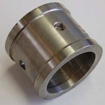 Image 1. Lantern ring (Images courtesy of FSA)
- environmental controls
- compression packing vs. mechanical seals
- leakage rates
- pump packing power consumption
- determining stuffing box dimensions
Lantern Rings
A lantern ring is used to supply or extract different media to or from the stuffing box (Image 1). It has a number of holes and is located under a bore in the stuffing box housing for external injection or extraction of media. It can be made from metals like stainless steel, carbon steel or bronze or from plastic materials like polytetrafluoroethylene (PTFE), PTFE/carbon and others. Often, the lantern ring is used to supply a water flush for cooling the stuffing box or to apply grease for additional lubrication. Depending on the application and type of media, the location of the lantern ring and its function in the stuffing box may vary. In Image 2, different examples are shown.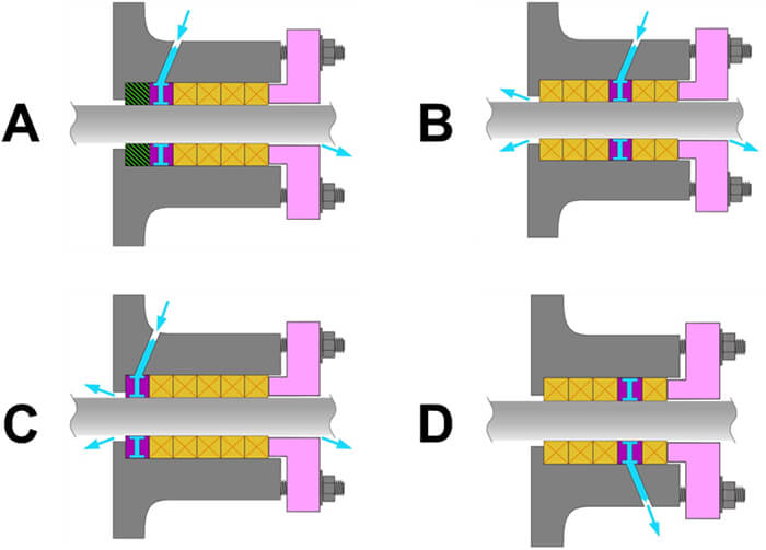 Image 2. Lantern ring arrangements
Packing Sealing Solutions Power
It has been assumed that pump packing friction and resulting power consumption is significant. In particular, it has been assumed to be significantly more than the power consumption of mechanical seals under similar pressure, size and speed conditions. An exhaustive study commissioned by the FSA and the ESA together with an extensive testing program completed by the Technical Centre for Mechanical Industry (CETIM) were conducted to verify this assumption, and it has proven that this was not accurate. The traditional theoretical power consumption of compression packings was given as: Equation 1: P = Pp x RPM x D x μ x Ap x F Where: P = power (horsepower or kilowatts, depending on units used) Pp = the sealed pressure RPM = rotational speed D = shaft diameter μ = coefficient of friction between the packing and the shaft Ap = packing contact area F = factor depending on units used Equation 1 gives power consumption estimates that were one to two orders of magnitude higher than what was experimentally measured. Torque, (and the resulting power consumption at a given speed), is a function of the type of packing used, the leakage rate allowed and the shaft speed and size. Based on extensive testing, a new formula for torque is given as: Equation 2: T = Pp * K * R * μ * Ap * S * Sp * F / L (Nm/ft.lb) Where: T = torque Pp = sealed pressure K = pressure drop factor R = shaft radius μ = coefficient of friction between the packing and the shaft Ap = packing contact area S = size factor Sp = speed factor L = leakage factor F = factor depending on units used In Equation 2, the packing types are divided into three classes based on representative packing type and leakage rates.- Class 1: PTFE, ePTFE/graphite
- Class 2: aramid, novoloid, carbon/graphite
- Class 3: natural (cellulosic) fibers, acrylic