Guidelines for reduced vibration and information on how a pump’s foundation and operating speed affect the vibration response
04/17/2014
Part One of this series in the March 2014 issue of Pumps & Systems discussed insights that may be gained by analyzing the mathematical model featured in “Top-of-Motor Vibration” (Pumps & Systems, September 2012). This second part expands on these insights and provides guidelines for reduced top-of-motor vibration, how the pump’s foundation influences vibration and discusses the impact of a pump’s operating speed.
Guidance for Obtaining Reduced Top-Of-Motor Vibration
Readers are reminded of the limitations imposed by the simplifying the assumptions discussed in Part One (first mode only considered, no other modes, no excitation sources other than imbalance). The information presented is provided as tools for insight and does not present a finished comprehensive work. It will assist in better understanding of vertical, wet-pit, column type pump vibration and help develop standard vibration acceptance criteria for the top-motor bearing. General guidance for achieving lower vibration levels includes the following:- To achieve reduced top-of-motor vibration measurements, an improved motor balance grade beyond standard is recommended. Motor manufacturers typically have a default standard balance grade but can offer a special balance with little additional cost. Pump manufacturers can assist specifiers regarding the level of motor balance grade that can be practically supplied for inclusion in the specifications.
- To achieve reduced top-of-motor vibration measurements for an installation, adequate frequency separation margins in the field are needed. To help assure lower vibration response for installations in the pre-construction stage, the most difficult challenge is predicting the expected structure reed frequency because this is not easily accomplished to the required accuracy. A simple method of calculating the structure reed frequency was discussed in the September 2012 article. An additional resource, the Hydraulic Institute’s ANSI/HI 9.6.8 Guideline for Dynamics of Pumping Machinery (soon to be published), also provides guidance on this topic. In ANSI/HI 9.6.8, the calculation method for the structure reed frequency presented is considered a “Level 1” analysis, whereas more accurate methods are discussed in ANSI/HI 9.6.8 for use when these methods are justified (guidance for making this determination is also discussed in ANSI/HI 9.6.8). Because accurate prediction of the structure reed frequency is so important to achieving reduced vibration, specifiers desiring a high degree of certainty of reduced vibration values may need to specify a higher level (more accurate) dynamic analysis to precisely predict the expected structure reed frequency. ANSI/HI 9.6.8 includes a discussion of the analysis methods available and sample specification templates that can be used in contract specifications to request the desired analyses.
- ANSI/HI 9.6.8 discusses motor reed frequencies and the effect they have on vertical structures. Sample specification templates are provided that can be used for contract specifications to request an impact test to determine the actual motor reed frequency prior to shipment.
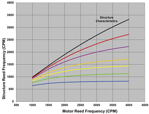 Figure 1. The structure reed frequency versus motor reed frequency—adapted from Figure C.2 of ANSI/HI 9.6.8, Dynamics of Pumping Machinery. Courtesy of Hydraulic Institute, Parsippany, N.J., www.pumps.org
Foundation Effects
For an installation with known field structure reed frequency characteristics based on tests, these test results will include foundation rigidity effects and no calculation of foundation effects is necessary. The ratio of the pump operating speed versus the actual structure reed frequency has a major impact on the vibration response. For pre-construction phase applications in which the actual structure reed frequency characteristics based on tests are unknown and must be calculated, the following approach may be used to apply the foundation effects to the mathematical model being discussed. Equation 1 is used to determine the structure reed frequency. Equation 1: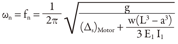 Where:
The denominator (also shown in Equation 2) = the static deflection of the structure at the motor’s center of gravity (CG)
(∆s)Motor and W = motor properties
L and a = dimensions
E1 and I1 = properties of the pump head (from the September 2012 article)
Equation 2:
Where:
The denominator (also shown in Equation 2) = the static deflection of the structure at the motor’s center of gravity (CG)
(∆s)Motor and W = motor properties
L and a = dimensions
E1 and I1 = properties of the pump head (from the September 2012 article)
Equation 2:
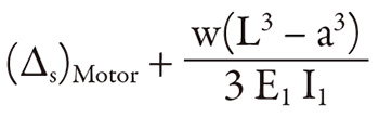 Adapting the definition for a rigid foundation as one that increases the static deflection of the structure at the motor’s CG by 5 percent or less produces the structure reed frequency shown in Equation 3 (an effect of 5 percent or a factor of 1.05 is used).
Equation 3:
Adapting the definition for a rigid foundation as one that increases the static deflection of the structure at the motor’s CG by 5 percent or less produces the structure reed frequency shown in Equation 3 (an effect of 5 percent or a factor of 1.05 is used).
Equation 3:
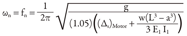 Introducing the factor of 1.05 to account for the foundation effects reduces the structure reed frequency to 97.6 percent of what would otherwise be obtained with no foundation effects included. Factors of greater than 1.05 for non-rigid foundation effects may be handled in a similar way, and the resulting structure reed frequency will be input into Equation 1 (from Part One). Using this information, the foundation’s rigidity impacts vibration indirectly through the frequency ratio (ω/ωn) in this rotating imbalance model.
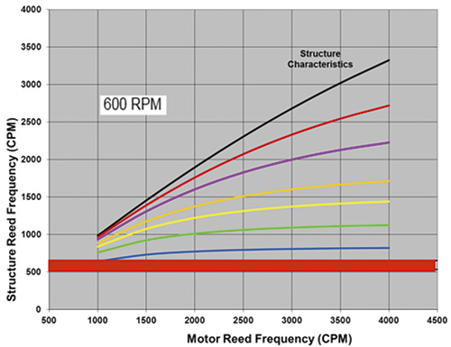 Figure 2. The structure reed frequency versus motor reed frequency at 600 rpm
Design Operating Speed Considerations
Satisfactory frequency separation margins are not easily achieved in applications that have certain design operating speeds (or motor speeds). These applications are more vulnerable to resonance and increased vibration because of typical structure characteristics and available motor reed frequencies. Conversely, avoiding resonance and experiencing lower vibration with some design operating speeds is easier when compared to others. Consider Figure 1. It shows the structure reed frequency versus motor reed frequency, with plots of different values of structure characteristics as defined in ANSI/HI 9.6.8. Figure 1 enables the structure reed frequency to be determined graphically using the motor reed frequency and structure characteristics.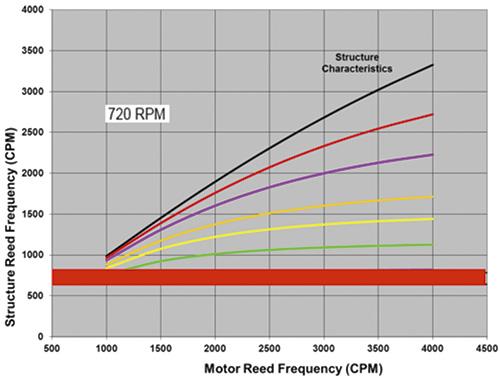 Figure 3. The structure reed frequency versus motor reed frequency at 720 rpm
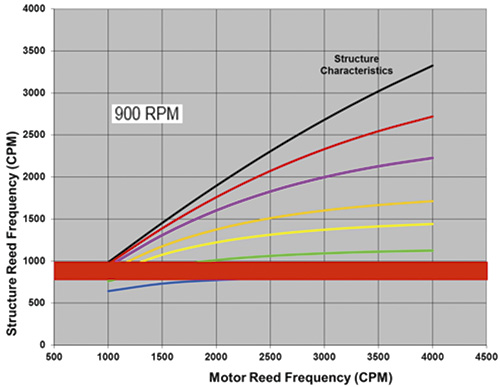 Figure 4. The structure reed frequency versus motor reed frequency at 900 rpm
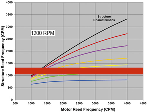 Figure 5. The structure reed frequency versus motor reed frequency at 1,200 rpm
Units of Vibration for the Purpose of Standard Acceptance Criteria
Units of vibration in terms of velocity are best used as the basis of standard vibration acceptance criteria, with velocity root mean square (RMS) being the industry accepted format. However, at some point, the design operating speed begins to move away from the typical structure reed frequencies encountered, with frequency separation margins increasing as the design operating speed decreases. This phenomenon can be understood from Figures 2 through 7 that illustrate the design operating speed considerations. At lower speeds, the frequency separation margins are far greater than the minimum recommended 10 percent, and the resulting vibration is very low—well below the velocity acceptance criterion that is useful at the higher speeds.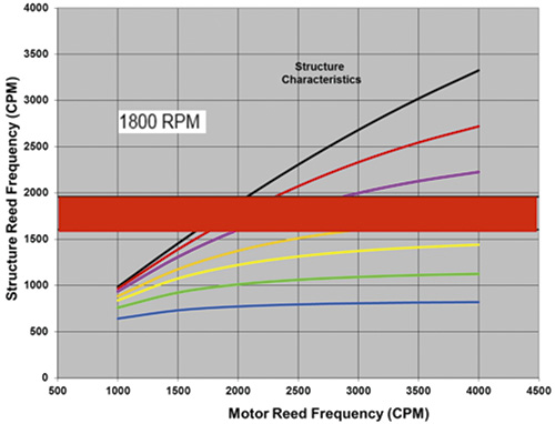 Figure 6. The structure reed frequency versus motor reed frequency at 1,800 rpm
Variable Speed Considerations
The proliferation of variable speed drives has added a challenge for the vertical pump industry pertaining to vibration. Space does not allow a discussion of this topic in this article series. Figure 7. The structure reed frequency versus motor reed frequency at 3,600 rpm
References
- Claxton, J., “Top-of-Motor Vibration,” Pumps and Systems, September 2012.
- ANSI/HI 9.6.8, Dynamics of Pumping Machinery, Hydraulic Institute (HI), Parsippany, N.J., www.pumps.org.