With the right setup, this software can open new possibilities for system and pump design improvements.
05/01/2015
Automated methods first emerged from the aircraft propulsion industry and became available to a wider audience in the mid-1990s. The first optimization products promised radical improvements in the design process but were expensive. With time, competition in the software market and a better understanding of the inherent limitations of the technique provided the industry with a more balanced perspective. While the revolutionary nature of automated optimization may have been overstated initially, many industries have adapted and evolved the technique in recent years. Today, automated optimization is widely used in engineering design and has moved into many spheres that have been late adopters of advanced numerical analysis.1
Optimization
Many optimization algorithms and commercial offerings are available to the engineering community. Some of the most prominent solution techniques include simulated annealing, genetic algorithms and neural networks. As the name implies, simulated annealing methods are derived from the natural annealing process of metals and glass. Generic algorithms mimic the process of natural selection. Neural networks are based on a network of processors similar to the neurons of the brain. Despite the sophisticated naming conventions and schemes, the basic goal is simple: find the combination of input values that yields the best result. The automated optimization process is highly dependent on what is defined as best, often referred to as the "objective function." The best schemes for optimization depend on the nature of the results and how they are distributed across the numerical space. Figure 1 shows a simulated annealing method in a simple two-dimensional variable space.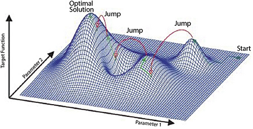 Figure 1. Simulated annealing response surface for a two-parameter example (Courtesy of Frankfurt Consulting Engineers GmbH)
Solution Methods
Anything that can be quantified through a model and has multiple inputs affecting the result can be used as the basis for optimization. In pump design, a typical option might be efficiency determined through a computational fluid dynamics (CFD) solution. However, any model such as meanline analysis or streamline curvature could be used to quantify performance, and finite element analysis (FEA) could be used to determine stress levels. Other more esoteric models can be also used in the objective function. Variables such as casting, machining or assembling costs can be used, provided they can be discretely quantified. Other phenomena such as noise, vibration and lifespan can also be studied. Combinations of analyses can be used to define the objective function. A common combination might be efficiency from a CFD solution and maximum stress level from an FEA analysis. Such approaches are called multidisciplinary optimization (MDO) and are common in practice. Most real-life manual designs require some compromise of several competing factors, and MDO methods can account for this in optimization. Special attention is required to constrain the model input and to scrutinize the model output for validity. A poorly chosen input range can force the model outside the valid range of results and render the process moot. A CFD solution that is not converged or has failed will give bad signals to the optimizer. Other constraints are often needed to ensure a rational result. A user can easily find that the result dutifully produced from the optimizer is either not manufacturable or has been driven to astronomical size if the proper constraints were not provided.Examples
This article will examine two CFD-based optimizations that demonstrate the optimization process (see Figure 2). The first study is an optimization of a three-dimensional volute. In the study, the flow rate was fixed and the overall head rise was predominantly determined by the impeller, which was also unchanged.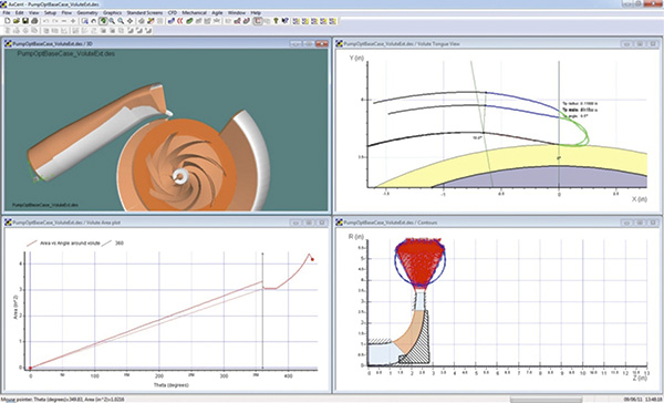 Figure 2. Three-dimensional volute (Courtesy of Concepts NREC)
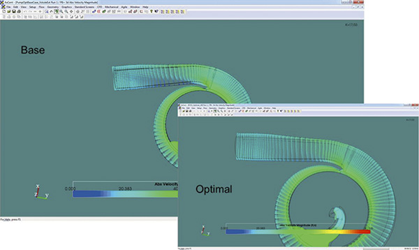 Figure 3. Flow field result for the baseline and optimized volute. Note the more uniform velocity distribution after the tongue. (Courtesy of Concepts NREC)
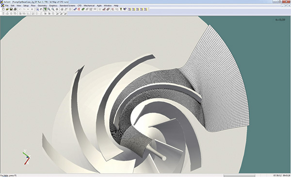 Figure 4. Cross-section of the structured grid example for the pump impeller optimization (Courtesy of Concepts NREC)
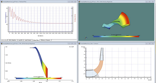 Figure 5. Solution for the pump impeller optimization (Courtesy of Concepts NREC)
Conclusion
Automated optimization is becoming more widely used in the turbomachinery industry at many levels. While commercial offerings have improved the process significantly, making effective use of optimization still requires expertise on the part of the user. That said, a properly designed optimization exercise can both streamline the entire design process and discover improved performance from regions of the design space that the user might never have considered previously. Expanded capability in modeling methods and reduced cost in high-powered computing resources both point to the increasing use of advanced optimization methods in the pump industry.
Acknowledgements
Dr. Edward P. Childs of Concepts NREC performed most of the optimization setup and analysis shown in this article and laid much of the ground work for the optimization system shown.
References
- Japikse, D., and Platt, M. J., "Optimization in Component Design and Redesign", 10th Int'l Symposium on Transport Phenomena and Dynamics of Rotating Machinery (ISROMAC-10), Honolulu, Hawaii, March 7 – 11, 2004.
- Anderson, M. R., "Optimization of Turbomachinery – Validation against Experimental Results," CDK Nové Energo, 2009 – Current Trends in Design and Computation of Turbomachinery, June 2 – 4, 2009.

