A comprehensive approach to reverse engineering helped to establish the differences between the stainless steel and original bronze impellers.
03/21/2016
When a severe pump failure involving one of three installed circulating water makeup pumps happened, facility personnel grew concerned about the root cause. The subject pump failed just 40 days after its commissioning.
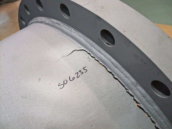 Image 1. A crack in the discharge head flange that involved fatigue failure of the weld of a pump.
 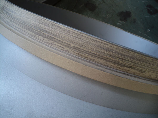 Image 2 (right). The pump's impeller wear ring landing shows heavy scoring.
Root-Cause Analysis
The line-shaft bearings and remanufactured bowl assembly were analyzed for mechanical and assembly root causes. The weld repairs were analyzed, and samples were sent to metallurgical laboratories for review by the end user. There were no apparent mechanical problems identified to point to the root cause of the failure. After extensive mechanical analysis of the failure, the company conducting the repair performed a comprehensive root-cause analysis of the failure. This involved analyzing the possible geometry differences of the replaced impellers and their influences on the pump hydraulic performance, which possibly caused the failure. Pump performance is determined and influenced largely by the geometry of the impeller and casing. If any changes to the geometry of these components occur, unintended consequences to the pump's performance can result.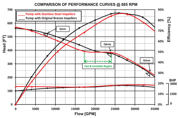 Figure 1. The chart shows the comparison of performance curves of a pump using stainless steel impellers and original bronze impellers. (Images and graphics courtesy of Hydro)
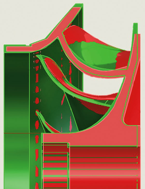
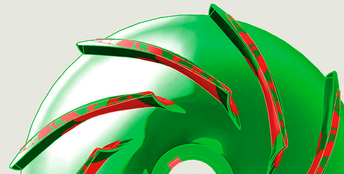 Figures 2 and 3. Reverse engineering shows differences between the stainless steel impeller, in red, and the bronze impeller, in green.
Geometry Comparison
Using a comprehensive approach to impeller reverse engineering, experts established the differences between the stainless steel and the original bronze impellers. Significant differences in the vane shape and at the vane exit and inlet (at the impeller eye) raised concerns about the impeller geometry (see Figures 2 and 3). The discharge vanes at the impeller outlet were considerably different, causing the discrepancy in head and curve shape. The inlet angles and geometry of the impeller inlets also showed significant deviations from the original design—meaning consequences for the machine's net positive suction head required (NPSHR). Based on the geometry differences at the impeller inlet, it was noted that the required minimum submergence level for the pump with the stainless steel impellers might be relatively higher than the required minimum for the bronze impellers. With this input, the plant reviewed the submergence data and confirmed the actual submergence level was at the minimum at the time of the pump failure. The minimum level for bronze impellers might not be sufficient for the stainless steel impellers, which could have compounded the problems of unstable operation and high vibrations.Pump Repair
Instead of repairing the cracks on the discharge head flange by welding, engineers suggested a spool piece design, manufactured and mounted onto the discharge head (see Image 3). The stiffening ribs added to the spool provided extra strength.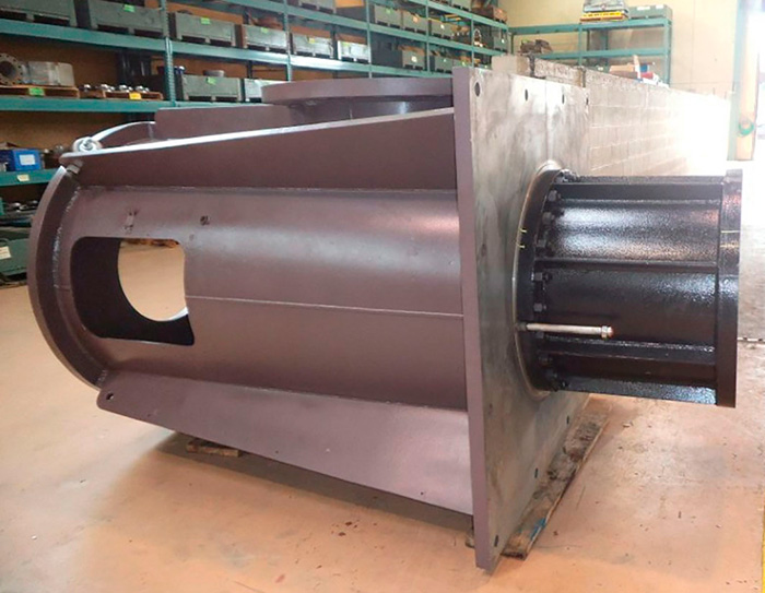 Image 3. Instead of repairing the cracks on the discharge head flange by welding, engineers suggested a spool piece design, manufactured and mounted onto the discharge head.
