

Back to the Future
Everything was fine and dandy in the pump world until 1970. Prior to that time, process plant designers, end users and pump manufacturers all agreed that providing a sufficient margin for net positive suction head (NPSH) fell into the “etched in stone” category of death and taxes. “You can’t avoid the grim reaper or the taxman, and you must pay the NPSH tax or the pump dies.” Prior to this, the plant/process designers placed the source supply tanks at high elevations and the pumps at low elevations (adding static head) in the quest to provide adequate net positive suction head available (NPSHa).
If you had to pick a date, it would probably be March 15, 1969, when someone at a plant (not involved in reliability) realized they could save a lot of money if future plants had the supply tanks and the pumps all at the same level. “Let’s get rid of these expensive elevated tanks and excavated pump locations,” they declared.
The plant owners’ team and the pump manufacturer’s team had a big meeting to seek a solution to the problem. The plant team decided that they liked the lower cost of building the facility all at one level, so the problem magically shifted to the pump manufacturers to lower the amount of net positive suction head required (NPSHr).
Back in the pump engineering department, it was decided that they could easily fix the problem. “We will just make the impeller eye bigger to reduce the NPSHr, and the problem will be solved,” they said. Introducing “big eye” impellers was the next best thing, and for a time, everyone thought the issue was solved, and the world was again at peace.
With the exception of gas availability and disco music, the 1970s weren’t bad. However, fast forward a few years, and the “big eye” pumps started failing prematurely. At about the same time, a young engineer named Jerry Hallam conducted extensive research that suggested a potential linkage between suction specific speed (Nss) and premature pump failures. Hallam subsequently published a technical paper/article in the April 1982 edition of Hydrocarbon Processing. The findings of Hallam’s research paper live on today, but often not in the manner that he intended. Some of his findings were misinterpreted and continue to be. I have covered the unintended consequences issue in several of my previous columns, and it is not my intent to explain further here. Suffice to say, in the modern era when Nss is approaching 11,000, it is but a yellow caution light and not a red stop sign. Please see my Feb. 2019 column with detailed explanations on the subject at pumpsandsystems.com/basics-suction-specific-speed.
Disclaimer
The previous paragraphs are purely opinion, partly fictitious, amalgamated and condensed for journalistic and comedic purposes, but the overall message remains true. Full disclosure, I don’t know if the ’70s were a good decade or not, as I was disconnected from the world, sealed away in a submarine.
You Can’t Always Get What You Want
Plant owners and end users want inexpensive pumps that will operate reliably over a myriad range of conditions, liquids and hydraulic coverage areas. Pump manufacturers would love to give users everything they want in a timely manner and at a fair market price, but the laws of physics and economics are standing guard at the transaction gate collecting tolls.
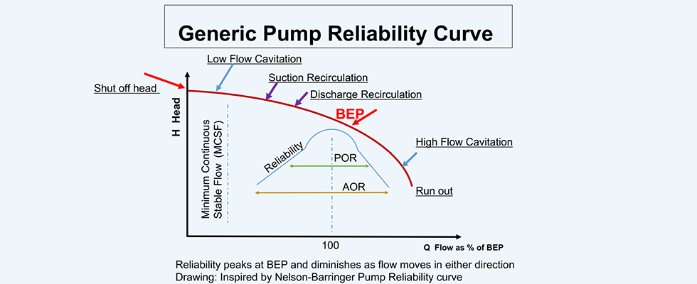
Centrifugal pumps are designed for only one optimum point of operation, which can normally be described as the best efficiency point (BEP) or area of shockless entry. All other hydraulic points of head (H) and flow (Q) on the published curve are a diminishing compromise defined as the preferred operation (POR) and allowed operation regions (AOR). These regions are defined in ANSI 9.6.3 by the Hydraulic Institute (HI). Yes, variable speed, impeller modifications, some system design aspects and certain material alloys will broaden the menu, but the limits remain (Image 1).
Cast & Fixed
For this column, we will be considering impellers in the specific speed (Ns) range of low to medium (450-7,000). Recognize that almost all pump impellers are castings, though some are fabricated, and they are normally cast in metal—although some are nonmetallic materials. Regardless of material or manufacturing method, the fact remains that the shape, the geometry, is fixed (cast).
Whether the casting is a simple sand mold or a sophisticated investment process, there is a high degree of involvement (expense) for any impeller recipe. At a minimum, the impeller production process includes engineering, drawings, tooling, patterns, molds, machining, labor, materials and, of course, the overhead of a foundry. Additional obstacles are present because foundries fall into the category of “not in my backyard” in a contentious relationship with environmental stewards.
Whack-a-Mole Matrix
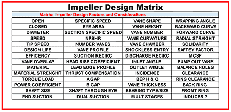
Like a good marriage, all pump design is about compromise. Not that your mother-in-law is coming to stay for a few weeks but from the aspect of economics, efficiency and reliability. And, like the game of “whack-a-mole,” any one attribute you manipulate over at point A will have an effect somewhere else. In the matrix of impeller design decisions, there are innumerable factors. See Image 2 (matrix) for some of the more important impeller design considerations and decisions. The X and Y positions I used in the matrix are random with no particular order or technical magnitude.
The heart of a centrifugal pump is the impeller. You design impellers to develop a certain amount of head (pressure, for the layperson) so the speed and diameter will be the key factors. We’ll talk about the flow rate in a later column, which is more a function of the impeller width (vane height) and speed. I have discussed casing/volute/diffusor designs in earlier columns, so I will not expand on that subject here.
Big Eye, Nss & Flow Recirculation
The interior of the casing suction nozzle, in combination with and in juxtaposition to the leading-edge profile and angle of the spinning impeller vane(s), is designed to align with and present the liquid flow to the leading edge of the impeller inlet vane at just the right time, with the right amount of flow and at the exact precise angle—all to manifest as shockless flow into the impeller, which in turn does its magic.
When manufacturers made the impeller eye bigger back in the ’70s (so the NPSHr could be reduced), the group thinking was the pump would of course function near the POR and all would be well. The issue is that pumps are rarely operated only in the POR. What happens at condition points left of BEP and POR is that flow recirculation will occur and create cavitation damage on the high-pressure side of the impeller vane regardless of how much NPSH is available. The phenomenon is known as discharge and suction recirculation cavitation. It is the potential danger highlighted in the aforementioned studies for impeller designs in the Nss range approaching 11,000 that are operated left and away from BEP going toward shutoff. Recirculation is also referred to as hydraulic instability and/or hydrodynamic cavitation.
Discharge recirculation damage occurs closer to the trailing edge of the impeller, which is closer to the discharge side, and suction recirculation damage occurs closer to the leading edge of the impeller, which is nearer the suction eye. Discharge recirculation is a function of impeller to cutwater/diffusor geometry while suction recirculation damage is more a function of impeller eye geometry. Note that both types of damage occur on the working/pressure side of the vane, which is on the opposite side of where normal cavitation damage (or as I call it, “classic cavitation”) manifests due to insufficient NPSH.
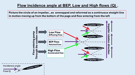
Incidence
Flow recirculation occurs in all pumps at some point of flow reduction when approaching shutoff head. In today’s properly designed impellers, we hope that recirculation occurs far left of the minimum continuous stable flow (MCSF) region.
The onset of recirculation occurs in the impeller as the flow rate is reduced, when operating at some variable hydraulic condition left of BEP. As flow is reduced, there will be a mismatch between the flow entry angle and the impeller angle, which is referred to as incidence. As the incidence increases, recirculation increases and continues to worsen until the flow separates. The flow separation causes a pressure differential, and some portions of the flow stream will actually reverse course. Yes, some portion of the flow will actually be exiting the impeller suction during operation. Each design will have a different point (flow rate Q) where this occurs. In general, minimum continuous stable flow boundaries will increase as Nss increases.
To understand what is occurring, it helps to realize that the overall pump discharge pressure increases as you move left on the curve, but also remember that as velocity increases, the pressure decreases inside the impeller—possibly below the vapor pressure of the liquid.
Recirculation in the impeller causes:
- Cavitation erosion on vanes
- Vibrations (high at low flows)
- Deflection (shaft)
- Vane damage (torque loads)
- Bearing damage
- Mechanical seal damage
- Reduced output
- Noise
- Suction gauge fluctuations
Nss: The Battle Between NPSHa & NPSHr
Salient points:
- Suction recirculation initiation point is not hard to calculate/determine.
- Discharge recirculation initiation point is hard to predict and calculate.
- Suction recirculation can be reduced but at the expense of NPSHr.
- Discharge recirculation can be reduced but at the expense of pump efficiency.
2025 Changes Today & Tomorrow
When considering pumps for present day projects, some users and engineers continue to use a Nss quotient to review or predict safe operating ranges based solely on Jerry Hallam’s 1982 article/paper. Consequently, they see the Nss level of 11,000 as a firm boundary and will not use a pump where the Nss is approaching or higher than 11,000 for water or sometimes 16,000 for hydrocarbons. Note that American Petroleum Institute (API) 610 used to suggest a higher acceptable threshold of Nss at 12,000, but I am not sure it still does. HI suggests an even lower Nss value for some but not all applications, such as paper pulp in the range of 7,500. (HI 9.6.1/9.6.3 and 14.6)
There have been numerous changes in pump and impeller design since the 1980s that erase or at least mitigate many of the previously stated problems. Many older pumps utilized slender (flexible) shafts with high length over diameter ratios (L over D ratios, also referred to as L3/D4). The shaft scores are like the game of golf where higher numbers are not better. The higher number implies a less robust shaft to mitigate radial thrust deflection at off BEP conditions. Consequently, shaft deflection will be higher, causing more issues with seals and bearings. Present day shaft designs are more robust where the L3/D4 ratios are much lower, often by factors of 3 to 6. The robust shaft designs also function to push first critical speeds higher.
In addition to shaft robustness, there have been numerous design changes and knowledge acquisition (empirically via testing and computer modeling), which has improved pump reliability in wider operating windows as Nss approaches or exceeds regions of 11,000:
- Quality of castings
- CFD analysis (3D versus 2D)
- Improved accuracy of NPSHr testing
- Leading edge vane profiles
- Vane inlet angle
- Vane overlap, number of vanes, vane thickness
- Testing, modeling and education on recirculation issues
- Standards: reduction of recommended inlet velocities
- Suction line enhancements and improved geometry guidelines
- Suction energy (SE) understanding
- Diffusors and volute cutwater geometry and profiles
- Dual suction
- Inducers
- Knowledge: recirculation issues as a function of pump energy/BHP
Not all of the old impeller designs were bad, and many were good. Many of the new impeller designs are very good but not all of them. So, like Sergeant Phil Esterhaus used to say on every episode of “Hillstreet Blues,” “let’s be careful out there,” and I’m still not a big fan of disco music. Guess you had to be there.
References
- Technical paper/article (April 1982 Hydrocarbon Processing), Jerry Hallam PE
- A Map of the Forest, Understanding Pump Suction Behavior, Proceedings of the 1st Pump Symposium, 1984, Igor Karassik (Oaktrust Library)
- Influence of Impeller Nss on Vibration Performance, Simon Bradshaw et al, 29th Pump Symposium, 2013 (Oaktrust Library)
- Pumps & Systems, 2011 series of articles on this subject, Terry Henshaw
- Centrifugal Pumps, Johann Friedrich Gulich
- Proceedings of the 5th Turbo Symposium, 1976, Dr. Elemer Makay (Oaktrust Library)
- Proceedings of the 2nd Pump Symposium, 1985, Dr. Paul Cooper et al (Oaktrust Library)
- ASME 1980, page 260, Prediction of Reverse Flow, Bruno Schiavello