As new design and manufacturing technologies are developed, end users can affordably upgrade their systems and verify better performance.
07/29/2015
The rising cost of electrical power has caused many industrial plants to shift their focus to energy consumption. Plants often run pumping equipment continuously, and much research has pointed to opportunities for cost savings by optimizing pumping equipment. When evaluating the potential for energy savings, end users cannot consider a pump in isolation. The suitability of the pump for the system within which it operates is vital. Even the best designed and most efficient equipment offers power-saving potential if it is run off its best efficiency point (BEP) in a system for which it is ill-applied.
 Image 1. Much research has pointed to opportunities for cost savings by optimizing pumping equipment. (Images and graphics courtesy of Hydro, Inc.)
The Starting Point
Pumps react to changing system conditions. System demand (or system resistance) determines the flow and pressure at which a pump will operate. As system flow demand increases, the flow throughput of a pump also increases, causing it to operate further on the right-hand part of the performance curve. The system demand is graphically represented by plotting the system resistance curve as a function of flow. This curve enables the end user to quickly determine system flow for a given pump since the pressure and flow are determined by the intersection of the pump performance curve (red) with the system head curve (green). A process design engineer would ideally select a pump with an operating point that would have coincided with the BEP. This could yield a pump efficiency of 80 percent, as shown in Figure 1.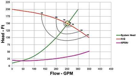 Figure 1. Pump and system curve interaction
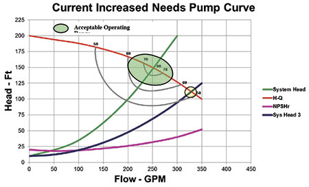 Figure 2. Pump Performance curve interaction based on different system requirements
Original Duty Point
The original system design for one processing plant's service water pumps was to have three pumps operating in parallel with an installed spare as a standby. The total system requirement was 105,000 U.S. gallons per minute (GPM) (23,864 cubic meters per hour) at a pressure of 190 feet (57.9 meters) total dynamic head (TDH). Each pump was rated for 35,000 GPM (7,955 cubic meters per hour) at 190 feet (57.9 meters) TDH. As production increased, more service water was required, causing the existing pumps to operate further out to the right of the performance curve. This caused the net positive suction head required (NPSHR) to exceed the NPSH available (NPSHA), leading to severe cavitation issues. To reduce cavitation problems, the plant ran four pumps in parallel and throttled each pump to keep the individual pump flows low enough to prevent cavitation.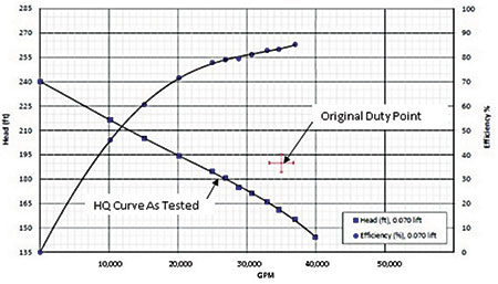 Figure 3. Pump performance test data illustrating performance degradation
New Impeller Design
The technological advances made in recent years with reverse engineering, laser digitizing equipment, computation fluid dynamics (CFD) software and the ability to print 3-D foundry molds from computer-aided design/computer-aided modeling (CAD/CAM) software has revolutionized the aftermarket industry. Solutions that were cost-prohibitive five years ago are now within the realm of financial feasibility. The solution helped manufacturers and end users solve their energy optimization difficulties in three ways: 1. Capture system resistance data and operating conditions. The plant's pumps operated at different flow conditions. Understanding how these flow requirements matched the system's resistance enabled an optimized design flow to be derived that would ensure that head was not generated by the pump to be dissipated over a control valve, so the number of pumps running was optimized for the demand. 2. Capture the geometry of the existing impeller using advanced laser-scanning equipment and build a CFD model of this impeller. This allows design scenarios to be evaluated to get the optimized design for the newly established flow conditions. 3. Use additive manufacturing in the form of 3-D foundry sand printers and casting simulation software to drastically reduce lead-time and overhead normally associated with pattern/core box sand casting processes. The 3-D printing process directly from the design data ensures that the integrity of the design is completely captured. The high accuracy of sand printing means that vane-to-vane symmetry and vane shape is identical. Sand printing also offers improved casting surface finish. These manufacturing measures alone can lead to a 3 percent efficiency increase. Tables 1-3 show the before and after energy usage, based on the projected energy audits.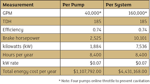 Table 1. Original system
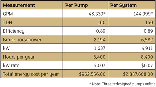 Table 2. Newly designed system
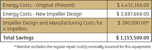 Table 3. Total projected energy savings for the system
Conclusion
Significant energy savings opportunities exist in every manufacturing facility worldwide, particularly with pumping systems that:- use pumps driven by 200 horsepower and above
- are primarily providing cooling water
- include demands proportional to the plant throughput
- are used for batch operations
- have inherent delays or production slowdown
- currently use dump valves or bypass lines
- feature fluctuating system loading