Editor’s note: For a more detailed analysis of the application and processes described in this article, check out Part 2 by clicking here. I recently received a comment from a reader who pointed out that all examples in my Pumps & Systems columns are small process systems with only one or two circuits. She asked if the same process could be applied to a larger system with multiple cooling loads in parallel. Looking back, most of the examples in my columns were selected to limit their complexity so I could concentrate on one aspect of the system at a time. This month, I will demonstrate how the same approach can be applied to a system of any size. Regardless of the size, arrangement or design objective, all piping systems are made of three primary elements. The pump elements add all the energy to move the fluid through the system, the process elements use that fluid energy to make the product or provide the service, and the control system improves the quality of the product. As we have seen, the head developed by all the pumps is equal to the head loss in the process elements and control elements in every circuit of the system. Most industrial plants have extremely large cooling water systems that provide water to hundreds of cooling loads. Balancing the energy in larger systems is tedious to calculate by hand, but computers can quickly handle these calculations. Software can be used to build piping system models and calculate the balanced flow rates and pressures, providing a clear picture of how a system works and what can be done to improve the system. This real-world example shows how a system energy balance was used in a large cooling water system in an industrial plant using such software.
The System & Challenge
During a software training course, an attendee presented a project involving his plant’s cooling water system. The system normally operated with two cooling water pumps providing sufficient cooling water to meet all plant loads. On a hot summer afternoon, one of the two operating cooling water pumps tripped. Staff immediately started the standby pump to return the system to normal operation before notifying the maintenance group. When electricians inspected the motor on the tripped pump, everything appeared normal. They notified operations after checking the motor loads on the two operating pumps and discovering their motors were operating well into their service factor. After a short discussion, operations personnel started the third pump and modified the plant’s operating procedure to operate all three cooling water pumps. With all three operating, the motor loads returned to satisfactory conditions. The plant’s operating guidelines state that for critical systems, the failure of one piece of equipment cannot cause the system to fail. The cooling water system was critical for continued plant operation, and with all three installed pumps operating, personnel took immediate action to purchase and install a fourth pump to provide the necessary standby protection. The plant engineer wanted to see if piping simulation software could determine if the changes would correct the problem. The engineer took steps to determine the cause and what could be done to return the system to normal operation as quickly as possible. The first step determined how the system would operate with three pumps. The plant cooling water system was needed to operate the plant, so operation of the physical system could not be modified. The plant engineer decided to use piping system simulation software to discover why the system required three pumps to operate instead of the initial two-pump operation.The System Model
An accurate model of the piping system was created using all available design data, manufacturer’s test and operating data. The flow diagrams and the piping and instrumentation diagram identified all major equipment and interconnected piping. The flow rate, head, efficiency and NPSHR as shown on the manufacturer’s supplied pump curve were entered for each pump in the circulating water system. The data for the system’s process elements were entered. Using the manufacturer’s test data for the installed heat exchangers, the team entered the head loss versus flow rate in the system model. Next, piping details such as pipe material, schedule, diameter, along with the valves and fittings, were entered. The density, viscosity and vapor pressure of the system process fluid were specified. This was a closed-loop recirculating system, so elevation and pressure at the surge tank were entered.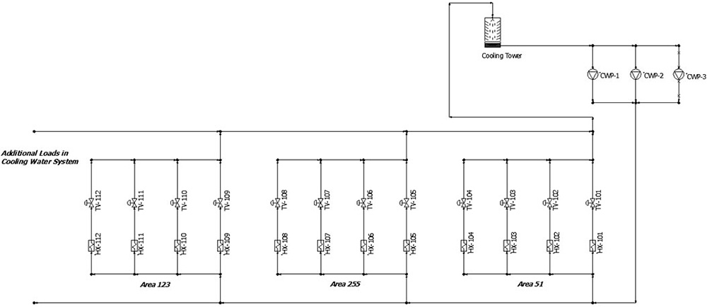 Figure 1. An example of the cooling water system described in this column (Courtesy of the author)