Pump System Improvement
08/02/2016
Editor’s note: This article provides additional information that further explains Ray Hardee’s monthly Pump System Improvement column appearing in the August 2016 issue. Click here to read it. Figure 1 shows 12 circuits of a much larger cooling water system. Like all piping systems, the total system consists of the pump elements, process elements and control elements. Each circuit in the system has each of the three elements. To demonstrate, we will follow the circuit on the right side of Figure 1.
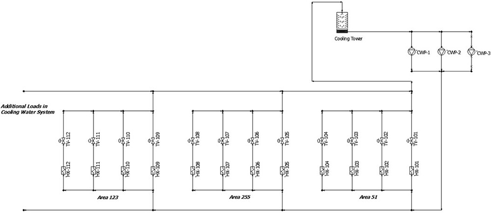
Figure 1. An example of the cooling water system described in this column (Courtesy of the author)
The circuit starts at the cooling tower, which serves as a pressure boundary and provides us with a location where the fluid energy is known. Because the cooling tower provides all cooling water for the system, it is shared by all the circuits in the total system.
Our example circuit continues from the pump discharge headers through a common supply header, then branches off to a common header for Area 51, where the system branches to process heat exchanger HX-101. Downstream of HX-101, the circuit continues with throttle valve TV-101. The throttle valve is positioned to set the rate through the circuit to the design flow rate. The circuit then proceeds through the various common return headers back to the spray header on the cooling tower.
In this system, the cooling water flow rate through each of the circuits is determined to remove the heat exchanger’s thermal load. This is accomplished using a temperature-control loop or by setting the position for all system throttle valves to a balanced position. The heat load in this cooling water system is constant so the system was designed using manually operated throttling valves.
A balancing contractor determined the position of each throttle valve by estimating a position to the throttle valve in each circuit. When the system was started, the flow rates were checked in each circuit within the system. In the circuits with flow rates less than the design value, the throttle valve position was increased. In circuits with flow rates greater than the design value, the throttle valve position was decreased.
What makes the process even more difficult is that changing the position in any circuit affects the flow rate through all circuits. As a result, the balancing contractor must arrive at a set of new valve positions after each pass and determine how they affect the flow rates through each circuit.
Early in my career, I was involved in manually balancing a cooling water system at a nuclear power plant. It took a team of more than 10 people about a week to balance the loads for all circuits to the designed flow rate indicated in the test procedure.
Recently, new loads were added to the cooling water system, and the flow rates through some existing loads were increased. As a result of the change in flow rate, the system was no longer balanced. After the addition of the new loads, the team decided not to employ the services of a balancing contractor. Once the cooling water system was placed in operation with the additional loads, the plant operators opened the throttle valves to increase the flow rate through the heat exchanger to maintain the proper outlet temperature. One thing the operators were not aware of is that each adjustment to a throttle valve in a circuit affected the flow rate in all circuits. As the operators continually adjusted the system, over time the flow rate through the system was much higher than the process requirements.
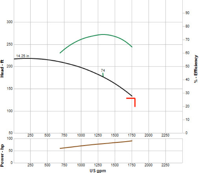
Figure 2 shows the pump curve for each pump when two circulating water pumps are supplying the system with all throttle valves fully open. Notice the flow rate through each pump is approximately 1,800 gallons per minute (gpm), overloading the motor. This resulted in the motor tripping on high current.
Figure 2. The pump curve for one of the operating cooling water pumps running prior to the loss of the cooling water pumps
As described previously, the operators immediately started the standby cooling water system. After they determined that the pump tripped on high motor current, the operators placed the third cooling water pump in service.
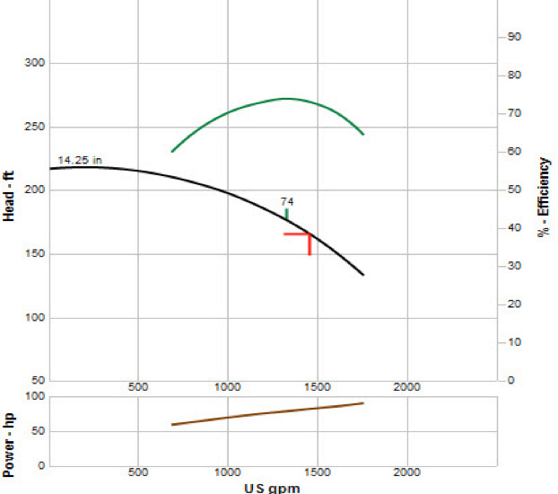
With three pumps in operation, the flow rate through each pump was reduced, but because three pumps were now operating, the system flow rate was higher. Figure 3 shows how a single pump operates when all three pumps are operated.
The pump curve shows that the head developed by the three pumps operating in parallel is 165 feet, with a combined total flow rate through the system of 4,400 gpm. The flow rate through each pump is operating to the right of its best efficiency point (BEP), but well within the motor’s duty factor.
Figure 3. The pump curve for one of the operating cooling water pumps running after the third pump is operated
After inspecting the system and discovering that all the throttle valves were fully open, the plant engineer wanted to see if it would be possible to balance the system at the new system flow rate. Using the design data for the cooling water flow rates through the heat exchanger, the plant engineer determined that the design flow rate through the entire system was 2,650 gpm.
Looking at the pump curve, he could determine the flow rate through each pump would be 1,325 gpm, resulting in the pump operating close to its BEP. Next, the engineer had to determine if the pumps could deliver sufficient head for all the circuits in the system.
Setting the flow rate in the piping system model to the design flow rates and operating the model with two cooling water pumps revealed that the existing pump head was sufficient for the design flow rate through all the circuits. In addition, the model provided the calculated valve position of each throttle valve needed to balance the system.
The calculation performed using the piping simulation software was similar to the steps carried out by the balancing contractor. The software performed an initial guess of the differential pressure needed across the throttle valves to balance the flow rate in each circuit to the design valve. Once the differential pressures across the throttle valves were calculated, the software was able to determine the position of the control valve needed to balance the system.
Checking the Results
The team decided not to change the position of the throttle valves when the plant was operating to prevent downtime. During a planned weekend outage, all the throttle valves in the cooling water system were set to the calculated position. To make sure the system was balanced, an ultrasonic flow meter was employed to validate the flow rate though each circuit with only two cooling water pumps operating. The test results of the physical piping system matched the design flow rates, indicating that the system was in balance. The test showed that the flow rate was balanced, but to ensure all heat exchangers met the thermal transfer requirement of each circuit, an operation test was planned when the plant was back in operation. Once the plant was in operation with only two active pumps the engineers checked the outlet temperatures of all heat exchangers. With the exception of two heat exchangers, the outlet temperatures were within the allowable temperature. The two heat exchangers with high temperatures and the design flow rate indicated that the heat transfer within the heat exchanger was not as designed. To ensure the plant operated properly, they increased the flow rates through the two heat exchangers until the outlet temperature was within the allowable range. By adjusting the throttle valve position on the two circuits that had problems with their heat exchangers, the plant engineer could determine how changing the flow rate through the two loads would affect the operation of the remaining circuits in the system. To accomplish this, he positioned all the throttle valves to the final position and performed a system simulation. The calculated results of the piping system model indicated that the calculated flow rates through each circuit were well within the range of system operation.
See more Pump System Improvement articles by Ray Hardee here.