Many may already be aware that pump system design involves making tradeoffs to minimize cost and maximize profit. But in the optimization process to minimize cost, it can be easy to neglect design aspects that keep the system safe and efficient in favor of others that help generate more profit. Here are three major aspects of optimization that should not be neglected.

Example Pump System No. 1
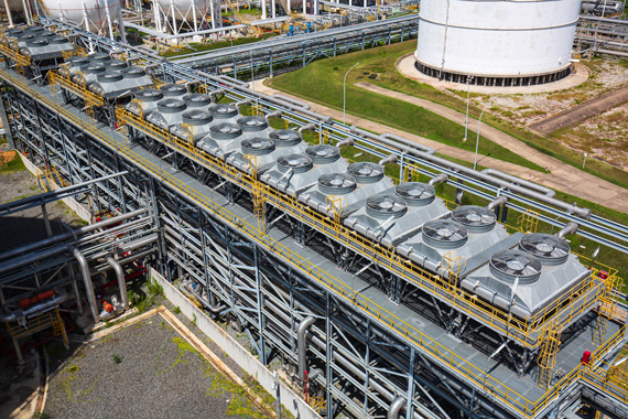
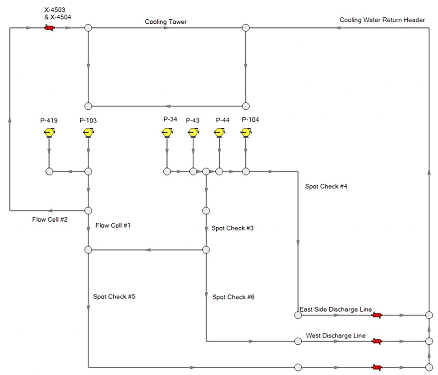
In this study of a petrochemical cooling water system, engineers were asked to address capacity shortages in an existing system. A sensitivity analysis was performed to determine what changes would be most effective, including valve settings, component replacement and several pump operational changes. Engineers recommended updating the components in one area to reduce the flow, which allowed the user to run fewer pumps in parallel and still meet the desired capacity. Overall, the user increased capacity and decreased maintenance costs, which would not have been possible if only the pumps had been analyzed. Image 1 shows a simplified overview of the system.
Takeaway point: Do not underestimate minor system components
The layout of the piping and equipment will most likely be dictated by the process and size restraints of the site. However, some flexibility may be available in the pipe sizes and minor fittings used in the lines.
Sizing pipes, minor fittings and the pump(s) used for the process should be done in tandem. There will not be one singular combination of equipment that can deliver the desired flow, head, etc. However, there will be some combination of equipment that will minimize cost while still meeting demand. It is tempting to save time by just selecting line sizes based on previous existing designs, then choosing the cheapest pump that will meet the user’s demands. However, it is unlikely that the previous designs were optimized, and thus, this method just perpetuates mediocre design choices made for convenience.
With the pipe flow modeling tools available in the market today, it is relatively easy to analyze many pipe size/pump size combinations in a short amount of time rather than relying on previous projects to make expensive equipment purchases. This could result in capital savings up front and savings on operating costs in the long term.
When working on updating an existing system, there will still be opportunities to improve the system. Remember, performance is driven both by the pump and piping configurations; therefore, changes should be considered to all components, not just to the pump. Any method to reduce system resistance can help increase pump output overall.
Example Pump System No. 2
In a separate study involving a cooling water system for a refinery, engineers determined the cause of excessive erosion in the suction side of the pumps.
After collecting data and creating a hydraulic flow model, the engineer determined the pumps were operating on the low end of the preferred operating region (POR), as defined by the American National Standards Institute/American Petroleum Institute (ANSI/API) standard 610 11th edition, which specifies the POR is 70% to 120% of best efficiency point (BEP). Most of the pumps appeared to be operating at about 73% on average based on the flow model.
Takeaway point: Do not ignore BEP
When choosing a new pump or evaluating the operation of an existing pump, it is important to operate as close to the BEP as possible. Operating near BEP reduces operating costs and decreases wear to the pump caused by heat and vibrations as the pump operates away from BEP.
To minimize damage, it is recommended to run the pump in the POR specified by the manufacturer or as is defined in the ANSI/API standard 610 11th edition. Several methods can help keep the pump operating within the POR. If the pump is operating far from BEP, the most efficient solution would be to run the pump at a lower speed to operate the pump as close to its BEP as possible. Using a variable frequency drive (VFD) can help control this speed change, especially during unsteady operation where the operating point will be shifting.
Impeller trimming would also be relatively efficient as it would lower the power consumption for the pump. However, impeller trimming allows much less flexibility for changes to be made later in the pump’s life cycle.
The worst solution power-wise would be to use a throttling valve. While the capital expenses for a valve are typically lower than a VFD, throttling the pump will require the full power consumption of the pump, which will be used to overcome the extra resistance at the added valve.

Example Pump System No. 3
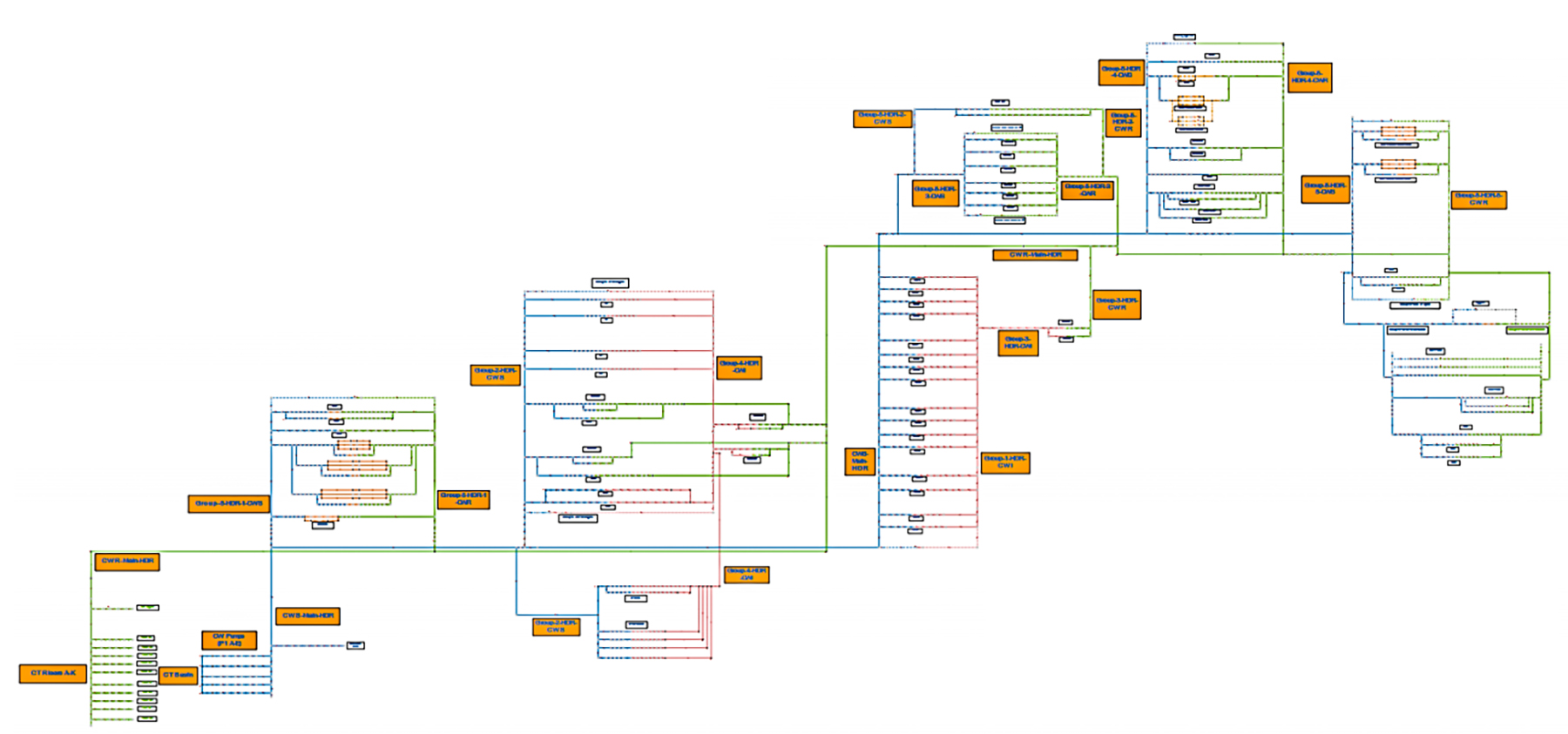
A new booster pump station was designed for a tailings management facility to increase the peak output from about 4,600 cubic meters per hour (m3/h) to 6,000 m3/h. To ensure safe and continuous operation of the pipeline, a surge analysis was performed to confirm that the maximum allowable operating pressure would not be exceeded at any point of operation. Additionally, stress analysis was performed to confirm the adequacy of pipe supports. The pipeline with the added booster pump station is shown in Image 2.
Ultimately, engineers were able to select booster pumps that would deliver the highest possible flow rate and avoid designs that would cause transient pressures above the maximum allowable operating pressure.
Takeaway point: Do not forget surge analysis
It is tempting to model piping networks as steady-state since normal operating behavior is designed to operate steadily. However, every system sees transient events that cause pressure surges such as system startup and shutdown, closing/opening various sections or tank filling/draining. Unexpected occurrences such as emergency venting, valve closures and similar cases should also be considered.
It is not enough to confirm that the states at the beginning and end of the surge events are reasonable. Transient events can cause high- or low-pressure waves that severely increase or decrease pressure in the lines. To avoid repair costs, include surge analysis during the design process, rather than after the fact, to allow early network changes. Proactive analysis can potentially eliminate the need for expensive mitigation options such as surge tanks or air valves when other elements (such as valves and pumps) can be modified.
The magnitude of the pressure surge will be impacted by factors like the steady-state operating conditions, the pump inertia, size and geometry of dynamic equipment such as valves. Using a VFD with the pump for a controlled startup/shutdown can also help to reduce the magnitude of pressure surges.
Optimization requires an overall system mindset to account for the impact each component will have on production. Since pump operation heavily depends on the piping and units the fluid is delivered through, many combinations of pump and piping configurations should be considered to achieve the best results. The design process should account for capital costs of parts, operating costs (especially for the pump) and safety concerns, especially during transient operation.

