HI Pump FAQs
Hydraulic Institute
01/03/2017
Q. How are vertical pumps used in power generation applications? A. Vertical pumps offer design flexibility that is not usually available with other pump types. The Hydraulic Institute categorized 10 unique vertically suspended (VS) pump types as shown in Figure 2.1.3. With the exception of VS 8, all VS-type pumps are suspended with the pumping element below grade, submerged in the pumped liquid. Vertically suspended pumps provide unique utility that dictates how and when they are used.
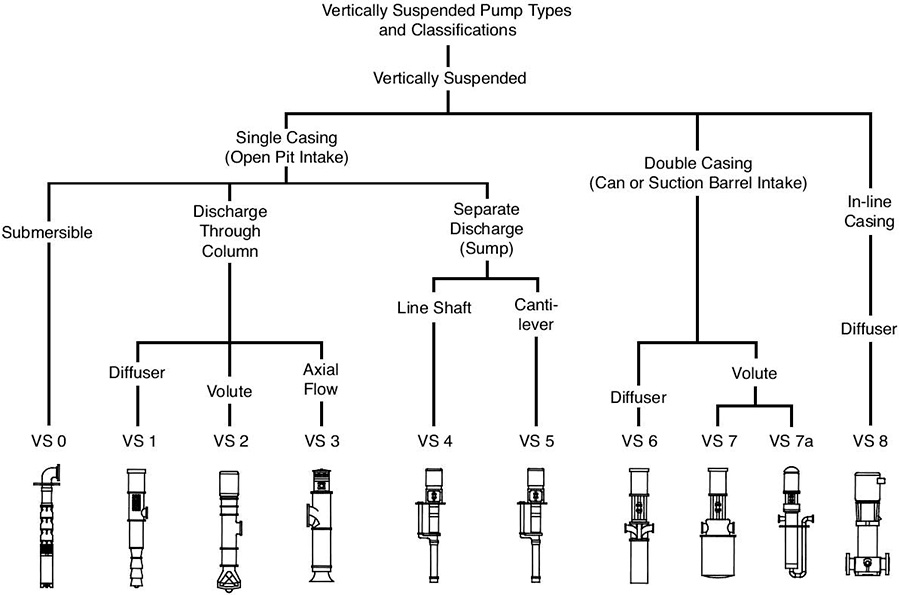
Figure 2.1.3. Vertical pump types—vertically suspended rotor—single and multistage (Graphics courtesy of Hydraulic Institute)
The depth of the pump setting can be selected so that the net positive suction head available (NPSHA) exceeds the net positive suction head required (NPSHR) at all times. This is a benefit in low-NPSHA applications such as pumps that take suction from a condenser hot well or heater drain.
The pumping element is normally submerged (in a wet pit or can), which eliminates the need for priming devices and enhances unattended reliable service. Plus, minimal floor space is required.
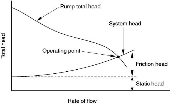
Many vertical pumps have characteristically steep head-versus-rate-of-flow curves. A steep head curve represents less rate of flow change with respect to head. A typical simple system curve and pump curve are shown in Figure 2.3.4.2. The pump always operates at the intersection point of the pump and system curves.
Figure 2.3.4.2. Pump performance versus system curve
Most manufacturers’ ratings curves are based on the bowl assembly performance.
In the range of intermediate specific speed, the maximum pump input power usually coincides with the recommended operating range and will not cause driver overload.
It is often possible to change the staging on the pump; that is, adding to (or subtracting from) existing equipment or changing impellers in the pump to meet design conditions.
For more information on the design and application of vertical pumps, refer to ANSI/HI 2.3 Rotodynamic Vertical Pumps for Radial, Mixed, and Axial Flow Types for Design and Application.
Q. What are the design considerations for condensate pumps in the power plant industry?
A. The major categories of pumps used in the power industry are boiler feed, boiler feed boosting, condensate, condenser circulating, boiler circulating and heater drain.
Specifically, condensate pumps take suction from a condenser hot well and discharge either to a deaerating heater in an open feedwater system or directly to the suction of a boiler feed pump in a closed system.
Condensate pumps operate at very low absolute suction pressures. Because the condenser hot well is often situated as low as possible to minimize the elevation of the power plant, the NPSHA is extremely low. This typically requires the use of the lowest practical elevation setting for the condensate pump (such as a deep pit).
The NPSHA, with absolute pressures in the condenser near zero, is the result of only the submergence (or elevation) between the water level in the condenser hot well and the centerline of the pump impeller (first-stage impeller for multistage pumps).
Figure 3.10. Vertical multistage can pump (VS6)
This value could be as low as 2 to 4 feet, which means that friction losses between the condenser hot well and the pump suction must be kept to an absolute minimum to avoid reducing NPSHA even further.
To minimize friction losses, calculated velocities in the suction piping and the suction can of vertical pumps should be no more than 5 feet per second.
Condensate pumps can be either horizontal or vertical, and single or multistage, depending on the system head requirements. Because of the low NPSHA, horizontal pumps operate at relatively low speeds.
Higher flow requirements may call for the use of larger pumps operating at 900 revolutions per minute (rpm) or less.
Vertical can-type pumps, which can be installed below ground and attain higher values of submergence of the impeller (higher NPSHA), can operate at higher speeds (see Figure 3.10). Vertical can-type pumps are available with single- and double-suction first-stage impellers and typically are furnished with 60-Hertz (Hz)/50-Hz four-pole and six-pole electric motor drives with running speeds at 1,780/1,490 rpm for low-flow applications and 1,170/980 rpm
for higher-flow requirements.
Condensate pumps are designed or arranged to have discharge pressure (or at least a positive pressure above atmosphere) on the seal chamber (or stuffing box) to prevent air from entering the pump.
If desired, pressure can be reduced through a throttle bushing at the bottom of the stuffing box and through an orifice back to the suction.
To prevent air leakage into an idle pump and to prevent the seal from running dry on startup, the seal cages of multiple pumps can be piped together and connected to a common pump discharge header.
To minimize vapor accumulation and entrainment, it is standard practice to vent the suction chamber back to the condenser above the water level.
For more information on pump selection in power plants, refer to HI’s guidebook Power Plant Pumps: Guidelines for Application and Operation to Maximize Uptime, Availability and Reliability.
See other HI Pump FAQs articles here.