Critical design improvements enable the promise of sealless pump technology
Twenty years ago, the managers of a wide range of manufacturing and liquid-storage facilities predicted that the industry was about to enter “the age of the sealless pump.” With stricter federal emissions regulations set to be introduced in 1992, this would have been welcome news for those in the petroleum refining, petrochemical, gas processing and chemical industries in which the use of hazardous/toxic materials or other pollutants was prevalent. Faced with tighter control guidelines for these types of emissions, plant and storage-facility operators needed a pump technology that could deliver the environmentally-sensitive, leak-free operation that they demanded, while also addressing maintenance and cost concerns.

Exploded view of the improved sealless gear pump
Extensive documentation existed to support the thesis that sealless pump technology was the answer in these applications. For example, in June 1990, a management-consulting firm produced a report for a leading manufacturer of industrial gear drives, pumps and compressors that predicted, among other things, that:
- The best available control technology (BACT) for most refining, petrochemical and chemical plants will be sealless pumps.
- The chemical industry is moving to use sealless pumps at a faster rate than the petroleum industry.
- The sealless market will be served two-thirds by magnetic-drive units and one-third by canned-motor units.
- The long-term answer to the new federal regulations will be sealless pumps.
- Sealless pumps will take an increased percentage of the market—probably 25 percent by 1995 and 50 percent by 2000.
A year earlier, a report titled “An Overview of BACT Guidelines for Centrifugal Pumps” was prepared by the South Coast (California) Air Quality Management District which noted the No. 1 BACT in terms of efficiency in controlling emissions in liquid-handling applications was sealless pump technology, which was “becoming increasingly important, especially in the handling of toxic and hazardous fluids.”
We now know that 1990 did not signal the beginning of the golden age of sealless pumps.
The technology—as it was designed and constructed at the time—was not reliable enough, with too many instances of failures that were brought about by bearing and load deficiencies that led to seal and leakage issues.
These deficiencies created an operational stigma that many manufacturers of sealless pumps are still trying to overcome today.
However after all that time, innovative sealless pump technology is available that eliminates the bearing and load concerns that affected the performance of traditional sealless designs.
This technology has the capability of creating a new category of sealless gear pump that not only eliminates leakage concerns that can compromise safety for both plant personnel and the environment but also allows the operator to move all types of liquids, from thin to extremely viscous and the hazardous to the benign.
This article will show how a fresh, clean-sheet approach to the conundrums inherent in traditional sealless pump design were confronted and led to the creation of a line of sealless gear pumps.
In short, these pumps increase product sealing reliability while eliminating the unacceptably high ownership, maintenance and environmental costs—as well as the reputational taint—that have dogged past sealless pump designs.
The Challenge
The leakage that occurs in traditional mechanically sealed pumps results in two types of prohibitive costs for plant operators: maintenance and environmental. According to the Hydraulic Institute, as much as 40 to 50 percent of the cost of owning a pump is spent after the pump is purchased due to maintenance issues. The leading causes of high maintenance in conventionally sealed pumps includes that associated with mechanical seal replacement and the premature wear of the bushings and close-fitting metal parts because of insufficient support of the pumping elements.
The environmental cost of leakage includes cleanup and potential local, state or federal fines that may need to be paid in extreme cases. Another non-monetary cost is the resulting bad press and community mistrust after a leak or accident occurs.
Leaks can create several costs:
- Replacement of the raw materials that are lost and the finished goods that are damaged
- Paying a firm to clean up the spill
- Disposal of the material cleaned up
- Potential slip-and-fall hazards
- Environmental compliance fines and fees
- Lowered worker morale
- The need to replace workers who may choose to seek employment elsewhere
As mentioned, any pump design that is deemed sealless must overcome the stigma that has been attached to the technology for more than two decades. In fact, while the reports cited above were trumpeting the use of sealless pumps, efforts began almost immediately to discredit the technology's effectiveness and reliability when handling hazardous or toxic materials.
A report entitled “Meeting Emission Regulations with Mechanical Seals” released in April 1990 by the Seals Technical Committee of the Society of Tribologists and Lubrication Engineers (STLE) stated that “eliminating seals in pumps is not the solution to emission controls.” The standards committee included seven leading seal manufacturing companies working in conjunction with chemical company clients. The report also stated “sealless pumps seem like the perfect solution but rely on bearings being lubricated by the product being pumped. Therefore, bearing problems result from converting to sealless pumps.” The seal manufacturers effectively removed themselves as the weak link and focused on the perceived and sometimes real bearing issues.
The report listed a number of perceived problems that were present when relying on the product being pumped for lubrication, including: the sometimes poor lubricity of the pumped product; high instances of costly downtime for in-shop repairs; and the elevated chance that leaks will still occur, which exposes plant personnel and the environment to the pumpage. As pump manufacturers rushed their sealless offerings to market, an overzealous sales force misapplied or over-applied their products. Initial failures, most common among high-speed centrifugal manufacturers lent credibility to the seal manufacturer's warnings. End-users became cautious. Those burned would hesitate to consider sealless technology again.
Then, most damningly, the report concluded: “Obviously, there is questionable, if any, benefit (of using sealless pumps) to the end-user who is genuinely concerned with the environment and his personnel."
Times Have Changed (So Have Sealless Pumps)
Traditionally, sealless gear pumps are designed with a cantilevered load where a large rotor gear is attached to the end of the pump shaft. As hydraulic force is applied to the rotor during pump operation extra pressure is put on the shaft and bearings. This pressure can lead to shaft deflection and increased bearing wear, which results in more rotor-to-casing or rotor-to-head contact wear. The result is reduced pressure and flow rate.
Secondly, traditional sealless gear pumps feature two fluid chambers—a hydraulic chamber in which the gears work and a second chamber for the magdrive coupling unit—that are joined together by a bracket, which also serves as a barrier between the two chambers. This complicated design requires that a portion of the material being pumped through the hydraulic chamber must be used to cool the magnets in the other chamber. These requirements result in a long, complicated pump with elongated, narrow flow paths and the need for more parts which makes the pump more expensive and difficult to maintain. This also limits the viscosity of the liquids that can be pumped, as well as the types of solids that can be handled.
The Solution
The approach to finding an ultimate solution to the sealless pump quandary removed the word sealless from the development process. When looking to create a gear pump that is affordable, controls leaks and reduces maintenance costs and environmental concerns, the first step is to identify the areas in which sealless pumps fall short and look for improvements. As mentioned, the No. 1 area in which traditional sealless pump operation is compromised is the bearings and how they interact with, and are affected by, the pump's cantilever load. The second step is to find a superior replacement for the two-fluid-chamber design that complicated the pump's operation and limited its fluid-handling range.
Taking these main concerns into account, and approaching the design process with an open mind, the result is a gear pump line that is sealless, not because the designers and engineers felt that it needed to be, but because its design enhancements led them to the conclusion that it would operate most effectively as a sealless pump.
This pump also features two design enhancements to overcome the long-time challenges of excessive bearing wear and a fluid chamber design that complicates operation and limits product range. These enhancements are:
Between-the-bearing support system—As opposed to the performance-robbing, one-sided support found in a cantilevered-load design that exists in traditional sealless pumps, the new gear pump supports the rotor and idler gears at three locations through the creation and incorporation of:
A patented eccentric spindle that is supported in the head, the crescent location and the back of the containment canister, eliminating much of the effects of cantilever load. In tests in which 200 psi of pressure was applied to the rotor, only 0.005 inch of shaft deflection occurred in this pump, compared to 0.056 inch of shaft deflection in a traditional sealless pump, giving the new design 11 times less shaft deflection.
Larger diameter materials that provide more rigid support for less shaft deflection and bearing wear. For example, a traditional 3-inch sealless pump will have a shaft that is 17⁄16 inch in diameter. The diameter of the new design's eccentric spindle is 2 inches.
Large, long radial bushings that support the entire length of the rotating element, which spreads out the hydraulic forces and allows the bushings to last longer. The new pump's bushings are also made of premium-grade carbon graphite that will last up to eight times longer than more common bushing materials.
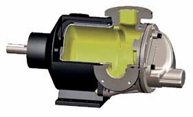
One-fluid-chamber design—As noted earlier, traditional sealless pump design features two fluid chambers that are separated by a bracket. This design creates operational difficulties while limiting the types of fluids that can be handled by the pumps. The improved design has only one fluid chamber with the pump's magnets placed on the back of the rotor and close-coupled, or “piggy-backed,” on the rotor gear. This design gives the pump a much shorter, simpler flow path. It also allows the pump to easily handle viscosities in the 20,000 to 30,000 cP range and as high as 50,000 cP, while still maintaining the ability to run thin liquids—such as caustics and solvents. These redesigned pumps can also pump liquids and slurries that contain solids.

Single-fluid-chambered sealless gear pump
Another feature that this design offers is dimensional interchangeability. These pumps have been designed to be interchangeable with 95 percent of the other gear pumps that are currently available on the market. This means that a plant can run a traditional sealed pump in the morning, have it pulled out in the afternoon and drop this single-fluid chamber gear pump into the footprint while reusing the same piping, gear box, motor and base plate, all while receiving the same hydraulic performance provided by the previous pump.
While this pump is designed to eliminate all the operational concerns found in old-style sealless gear pumps, its simple design—which consists of only seven primary parts: a magnet housing, containment canister, casing, rotor magnet assembly, eccentric spindle, idler gear and head—greatly reduces maintenance and environmental costs.
Conclusion
In the end, the design of these new sealless gear pumps makes them beyond a traditional sealless pump. They are an engineered solution for environmentally conscious fluid-handling that lowers maintenance costs and eliminates environmental costs.
Pumps & Systems, November 2011
Click here to see a Readers Response for this article.

