The ability to operate a parabolic machine—such as a boiler feed pump in a power plant—at variable speeds while following the pump curve is now considered a highly efficient method of operation. Many power plants are opting to retrofit fixed-speed boiler feed pumps to variable speed fluid couplings, a change that has the potential to save on energy and maintenance costs. Further, the couplings can provide space savings, allowing limited footprints to be used efficiently. Cost savings can be achieved with the flexibility of variable speed fluid couplings, along with the process changes that are instituted when they are added to a system. When installed in a combined-cycle power plant with an output greater than 500 megawatts (MW), the retrofits typically have a payback period of two years or less.
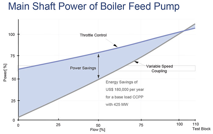
 Image 1. Variable speed pump operation versus operation of the same pump at fixed speed (Images courtesy of Voith Turbo North America)
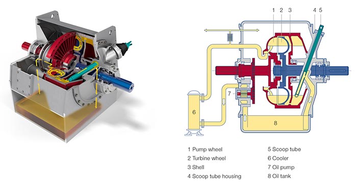
 Image 2. A variable speed fluid coupling and its parts
Operating Principles
In the typical scenario, the drive motor is started and brought up to speed. Oil is then pumped into the rotating primary wheel or annular chamber and collects centrifugally along the inner diameter of the shell. The oil is accelerated by the rotating primary wheel, converting the mechanical energy of the drive motor and primary wheel assembly into kinetic energy. The oil is then accelerated into the secondary wheel. As the oil reacts against the secondary wheel, the kinetic energy is converted back into mechanical energy, and power is transmitted between the two wheels. The amount of power transmitted is regulated by controlling the amount of oil that passes between the two wheels. As power is applied to the load from the boiler feed pump, the output shaft begins to rotate. The amount of oil allowed to remain in the rotating section of the coupling is controlled by the position of a scoop tube, which is inserted into the rotating shell. The more oil delivered to the “circuit” between the primary and secondary wheels, the more power is transmitted. As the transmitted power increases, the rotating speed of the driven machine also increases. Likewise, with decreases in the amount of oil in the circuit, the speed of the driven machine also decreases. Effective speed control is achieved by the position of the scoop tube in the rotating equipment and changing position as required. A control loop that monitors pump speed versus the coupling scoop tube position is the typical control scheme.Variable Speed Benefits
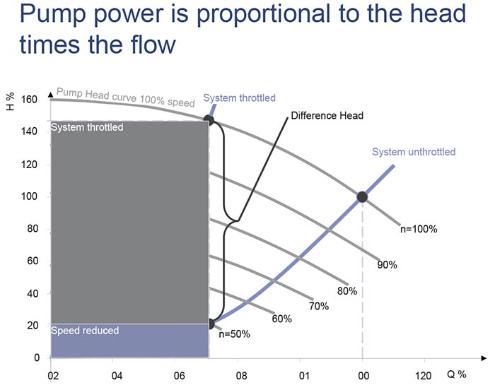
Operation of the pump at fixed speed in all required flow conditions results in the motor consuming the same level of energy in all conditions. When the flow of the pump is throttled, large portions of that energy is wasted. The valves used to choke off the flow can experience internal wear from cavitation and become an expensive maintenance issue. Image 3. The energy consumption for a fixed-speed operation versus a pump driven by variable speed
- stepless speed variation over a wide speed range
- load-free starting for electric drive motors
- limited torque transmitted from hydrodynamic circuits to ensure protection of drivetrain equipment
- reduced speed operation much of the time for boiler feed pumps, which can reduce wear within the system and extend maintenance intervals
- changed rate of speed follows the requirements of the process
- torsional dampening from the hydrodynamic circuit
- reduced transient torque spikes
- eliminated need for a freestanding lube oil skid because all lube oil is provided for drive motor and pump

