07/31/2014
Q.What are “nonclog pumps,” and in what applications are they used?
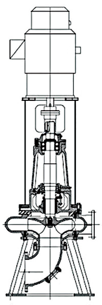
Figure 1. Dry pit pump – overhung flexibly coupled vertical end suction
A. “Nonclog pumps” are rotodynamic centrifugal pumps that are designed to ensure maximum freedom from clogging when handling liquids containing solids or stringy materials. These pumps are often used in wastewater services.
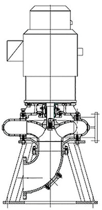
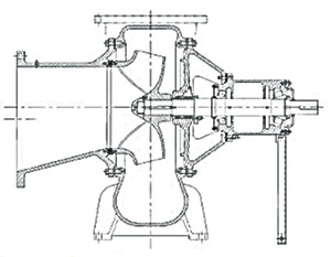
Nonclog pumps are also called dry pit pumps and are recommended for handling raw or unsettled sewage, activated sludge, industrial wastewaters containing solids, and similar liquids where excessive clogging would otherwise occur. Dry pit pumps come in a wide range of sizes and may use standard motors. They are available in horizontal or vertical configurations for space-saving considerations. Pump types OH1, OH3A and OH5A are generally applicable. These are single stage, overhung, horizontal foot or frame mounted, or vertical frame mounted—including close coupled, flexibly coupled or independently mounted motors with extended universal joint shaft drives (see Figures 1 – 3). All configurations commonly use nonclogging impellers.
These pumps can be quite large in capacity and dimension. Flow rates can exceed 200,000 gallons per minute (45,000 cubic meters per hour); heads can go up to 300 feet (90 meters); and discharge nozzle sizes can range from 3 inches (75 millimeters) to 72 inches (1800 millimeters).
Figure 2. Dry pit pump – overhung close coupled vertical end suction
Dry pit pumps are popular because they are easy to maintain, and their pumping problems are easy to diagnose. For sewage applications, the pump can be serviced without pulling the pump from a pit, reducing the amount of decontamination required. Comminution and/or adequate bar screens are necessary to prevent large solids from entering the pump. Operators should choose bar screen opening sizes that will prevent clogging from irregularly shaped solids. For sewage service, pumps are usually built to the manufacturer’s material specifications.
Figure 3. Dry pit pump – overhung foot mounted flexibly coupled horizontal end suction
Corrosion-resistant and wear-resistant shaft sleeves and wearing rings maximize life. Inspection openings in the casing or adjacent piping offer access to the impeller. Stuffing boxes may include mechanical seals or packing, either water or grease lubricated. When using water for the stuffing box or wearing ring lubricant or flush, the supply line must be separate from any potable water system.
For information on other applications for rotodynamic centrifugal pumps, see ANSI/HI 1.3 Rotodynamic Centrifugal Pumps for Design and Application.
Q. How should pressure-measuring instruments be configured during a rotary pump test?
A. The following precautions are necessary when forming orifices for pressure-measuring instruments and making connections:
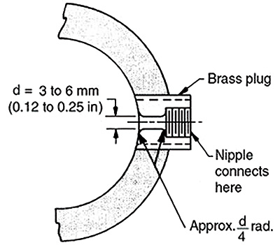
Figure 3.6.9a Pressure tap opening with corrosion-related plug
- The opening in the pipe should be perpendicular to the wall of the liquid passage.
- The wall of the liquid passage should be smooth and of unvarying cross section for a distance of at least the larger of two pipe diameters or 12 inches (300 millimeters) preceding the orifice. All tubercles and roughness should be removed with a file or emery cloth.
- The opening must be of a diameter between 0.125 and 0.25 inches (3 to 6 millimeters) and a length equal to twice the diameter.
- The edges of the opening should be provided with a suitable radius tangential to the wall of the liquid passage and should be free from burrs or irregularities. Figures 3.6.9a and 3.6.9b show two suggested arrangements of taps or orifices in conformance with the above.
- Manometers, when used on very viscous products with wet lines interfacing directly or indirectly, require larger inlet taps into the pipeline to avoid excessive lag time for fluid to stabilize in the measuring system.
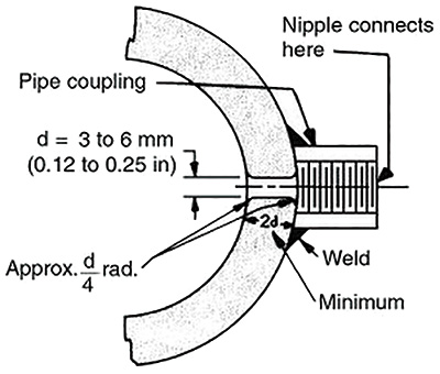
Figure 3.6.9b Welded-on pressure tap opening
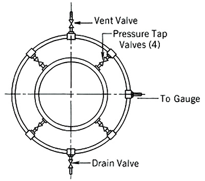
Where more than one tap or orifice is required at a given measuring section, separate connections, properly valved, should be made. As an alternative, separate instruments should be provided.
Multiple orifices can be connected to an instrument, except on those metering devices such as venturi meters, where proper calibrations have been made.
Figure 3.6.9c Loop manifold connecting pressure taps
The multiple orifices can be connected to a manifold and then to an instrument. With four or more pressure readings, there will be no more than 1 percent pressure variance between readings (see Figure 3.6.9c).
All connections or leads from the orifice tap should be tight. These leads should be as short and direct as possible. For dry-tube leads, suitable drain pots should be provided, and a loop should be formed high enough to keep the pumped liquid from entering the leads. For wet-tube leads, vent cocks for flushing should be provided at any high point or loop crest to ensure that no leaks occur.
For additional information regarding rotary pump test procedures, see ANSI/HI 3.6 Rotary Pump Tests.