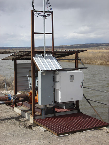
An important lesson to learn when working on, applying and technically supporting variable frequency drives (VFDs) is that the VFD is only one part of an overall system. The overall system has a desired operational purpose, and in order to achieve this purpose, all the parts that compose the system must be installed and utilized correctly and operated within their individual limits. The system can be simple, with only a few components and variables, or complex, with multiple variables and a complex assembly of various components.
To better understand the pumping system, there are many professional geologists, metallurgists, hydrologists, chemists, well drillers and operators who contribute to the overall knowledge of this application. It should be encouraged to attend some of the professional lectures available to hear them speak firsthand about how individual parts of the system can have a profound influence on operational results.
Understanding the Variables of the System
The system refers to anything that can affect the desired result of operating the system. Even the simplest of groundwater systems would include:
- borehole construction and efficiency
- electrical supply
- borehole geology
- static and pumping water levels
- overall size of the system
- type of pump
- size and frequency of demand changes
- friction losses from valves, elbows and the piping itself
There are numerous instances of misoperation on VFD controlled systems that had nothing to do with a malfunctioning VFD.
Case Study A (Remote Support)
In a conversation with an end user who had used their VFD system for a couple of years, they reported they were not getting the same flow rate they used to get at a given motor speed. This is a typical circumstance where the VFD gets the blame; however, if the pump is going the same speed as before but the output has changed, then something in the system has changed.
Possibilities could be pump wear, screen fouling, falling water table level or VFD misoperation. In this case, it was determined the pumping level of the well had dropped, which increased the total dynamic head required to produce the same flow as in previous years. This is a condition of physics and the only way the VFD can compensate is to increase speed.
Case Study B (Remote Support)
Experience is a powerful teacher and can provide a user with useful tricks and insights when troubleshooting pumping problems remotely. No matter the experience and/or expertise, a user must be on guard against their own hubris and confirmation bias or looking for evidence to confirm an unfounded conclusion.
An experienced salesperson called tech support late one evening after working on a VFD controlled pump startup on an orchard, attempting to settle down an erratic VFD controlled proportional integral (PI) loop. They had been at it for over an hour. The feedback was still fluctuating around the set point four to five pounds per square inch (psi), which resulted in significant pump speed fluctuations. Tech support believed the problem to be simply better tuning of the PI loop, but quickly exhausted all the tricks normally used for such matters and were stumped.
At this point, the decision was made to run the system in manual mode (hand mode) so the pump speed could be fixed at a known safe speed. This removed the PI function from the equation while still being able to observe the feedback pressure and motor speed. Once the pressure stabilized, the pump speed was dropped a small amount—2 hertz (Hz) (120 rotations per minute [rpm] on a two pole 60 Hz motor)—enough that it should have dropped the pressure feedback slightly. Several things can be observed in this process:
- Does the drop occur evenly and settle on the new feedback level?
- How long does it take for this change to occur?
- Does the feedback level remain stable?
In this case, after the speed had been dropped, it took several minutes for the pressure feedback to drop, which was not expected. Then the speed was increased back to the original speed setting and resulted in the same amount of time to increase the pressure feedback. When asked to explain this unexpected result, the salesperson replied it might have been due to the pressure transducer being located at the sprinkler head, which was over a mile away from the discharge of the pump. A radio link was used to send the pressure feedback signal to the VFD due to the distance. This meant the time to reflect any change in feedback caused by a speed change would be delayed by the sheer distance between the feedback device and the discharge of the pump.
The lesson to learn is to understand the system. The final solution in this case was a balance of extending the acceleration/deceleration time, PI tuning and placing a limit on the PI integrator input. This still took over an hour to complete. The system remained slow to stabilize and still rung around the set point a small amount and was deemed acceptable given the delay in feedback response.
Case Study C (On-Site Support)
A farmer with a 300 horsepower (hp) vertical turbine pump said the VFD was not working as well as before with water production down from previous years. A tachometer was attached to the motor, and it determined the motor was running at rated maximum speed and the water table had not dropped enough to account for the reduced production. After asking questions about the time interval of well rehabilitation, which had never been done, an inspection of the filter screens was carried out to see if they might be clogged.
Once removed, they were mostly clear with the exception of small debris consisting of 1-to-2-inch strips of black plastic resembling machine shavings of black Delrin. While the user could not explain its presence in the screen, it was clearly not the fault of the drive and was certainly not a product of geology. The primary suspect would be a serious pump problem that would require the removal of the pump from the borehole.
Case Study D (Remote Support)
A distributor called looking for assistance in troubleshooting an 800 hp vertical turbine pump with a 150 hp booster pump, saying the VFD would go into overvoltage protection and occasionally an overcurrent shutdown when operating near full capacity. Overvoltage faults on water pumping systems are rare, but can result from overly aggressive PI settings, water hammer or downhill pumping.
After some time with the distributor on-site and experimenting with different settings for acceleration/deceleration, S-curve settings and PI settings without improvement, the distributor was asked to watch the VFD monitor displaying the direct current (DC) bus voltage. They reported it appeared to vary widely and was not stable. Normally under load, a drop in dc voltage of 20 to 30 volts to a lower stable value would be expected on a 460 VAC system.
When asked to look at the utility pole transformers that supply power to this system and provide the kilo-volt-amperes (kva) values listed on them, the calculations of the kilowatt (kW) (power) available was revealed to be undersized to supply the expected maximum load of 950 hp. The calculations were supplied to the user and ultimately to the utility company engineer. In a conversation with the engineer, they were adamant the system had worked fine for years with the previous VFD of the same size and that the farmer was going to be liable for the $25,000 it would take to upgrade the system. No mistake in the calculations was identified by the utility engineer, and the only reasonable conclusion was that the transformers were undersized for the load.
In a follow-up conversation with the distributor on the engineer’s insistence that the previous VFD worked fine for years, they stated the previous drive was plagued with problems from startup and when it failed for the last time, it had exploded and nearly burnt down the pump house.
Other Possible Failure Points
1. Pressure transducers
- incorrect scaling
- incorrect positioning, such as too close to valves
- misconnected wiring
- fouling of orifice
2. Motor issues
- wired in reverse rotation
- miswired, such as incorrect winding connections for the operating voltage
- loose connections or wire nuts
3. Pump issues
- pump is worn or damaged
- improper sizing
4. Borehole problems
- biological fouling of the screen or gravel pack
- poorly designed or constructed borehole
- lack of regular maintenance
5. Electrical supply issues
- transformers too small
- voltage imbalance
- impedance imbalance supplying the VFD, such as open delta supplies
- distorted and unreliable utility supply, brown outs, phase loss, spikes
- lightning
While a VFD will add a level of complexity to a pumping system, the value added in being able to contro and troubleshoot it outweighs this challenge. A VFD does not guarantee energy savings, but it will allow users to use only the water they need and only the power needed to produce it. The VFD is only a single part in an overall system and all parts must work together to achieve the operational goals. Troubleshooters should understand the system, and if it is outside their understanding, they should ask for assistance.
Troubleshooting Basics
- Understand the system.
- Understand the history of the problem.
- Isolate components, if possible, to see if the problem is affected positively or negatively.
- Use a manual speed mode (hand) to eliminate PI issues and observe system response time to changes.
- Check the electrical supply.
- Check that electrical connections are correct, secure and routed correctly.
- Evaluate borehole condition.
- Call for assistance when stumped.

