Isolation valves, centrifugal solids separators and clean-in-place connections improve thermal performance.
10/15/2015
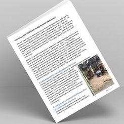
An equipment provider received a phone call from a disgruntled user. The company thought their process cooling system was not working properly. They requested that someone come look at it immediately. The equipment provider made a trip to the site for troubleshooting. The system, sized for 320 gallons per minute (gpm), consisted of a hot side closed loop system serving the process and a cold side open loop system with a cooling tower to dissipate heat. The two loops shared a plate and frame heat exchanger, and the pumps were fitted with typical trim—wye strainers and isolation valves on the pump suction, isolation and check valves on the discharge.
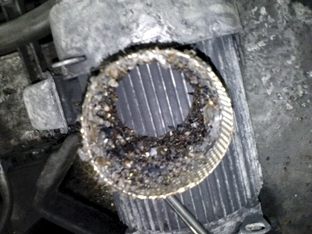 Image 1. Debris in the mesh prevented the system from functioning normally. (Courtesy of Fluid Cooling Systems)
Heat Exchanger History
What happened in this system, and how can the system be designed to optimize service intervals? To understand this, the history of heat exchanger design and selection must be examined. For many years, the standard practice of the process cooling industry was to use a single pass shell and tube heat exchanger with marine waterboxes to dissipate heat (see Image 2). The design of the heat exchanger is simple and straightforward: A series of tubes are rolled into a flat tubesheet, and the tube bundle, complete with baffles, is inserted into the shell.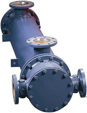 Image 2. The standard design for heat exchangers (Courtesy of Xylem Bell and Gossett)
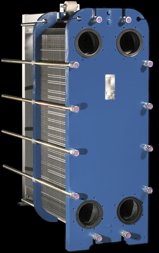 Image 3. A plate and frame heat exchanger (Courtesy of Sondex, Inc.)
Filtration Solutions
A common solution implemented on open-loop systems is to install barrier-style filtration, often in the form of basket or wye strainers. The issue with this configuration is rapid blinding of the filter media as illustrated by the previous example. A typical solution is to install enhanced surface area filtration, often in the form of duplex basket strainers. This increases the service interval by the percentage increase of surface area. For example, a 100 percent increase in surface area equals twice the interval between cleanings. The optimal solution, however, involves the application of a full-flow centrifugal solids separator. Centrifugal solids separators remove up to 98 percent of solids in a single pass down to 75 microns in size with a specific gravity differential of 2.6. Separation is accomplished through centrifugal force. Fluid is introduced to the separator tangentially, and the induced "cyclone" forces heavier particulate to the outside wall, where it is carried down the body to a settling chamber. The particulate is then purged on regular intervals or collected in a media filter via constant purge. Vanes and blades are often added to enhance separation efficiency, because lighter solids require more time in the vortex to effect separation (see Image 4).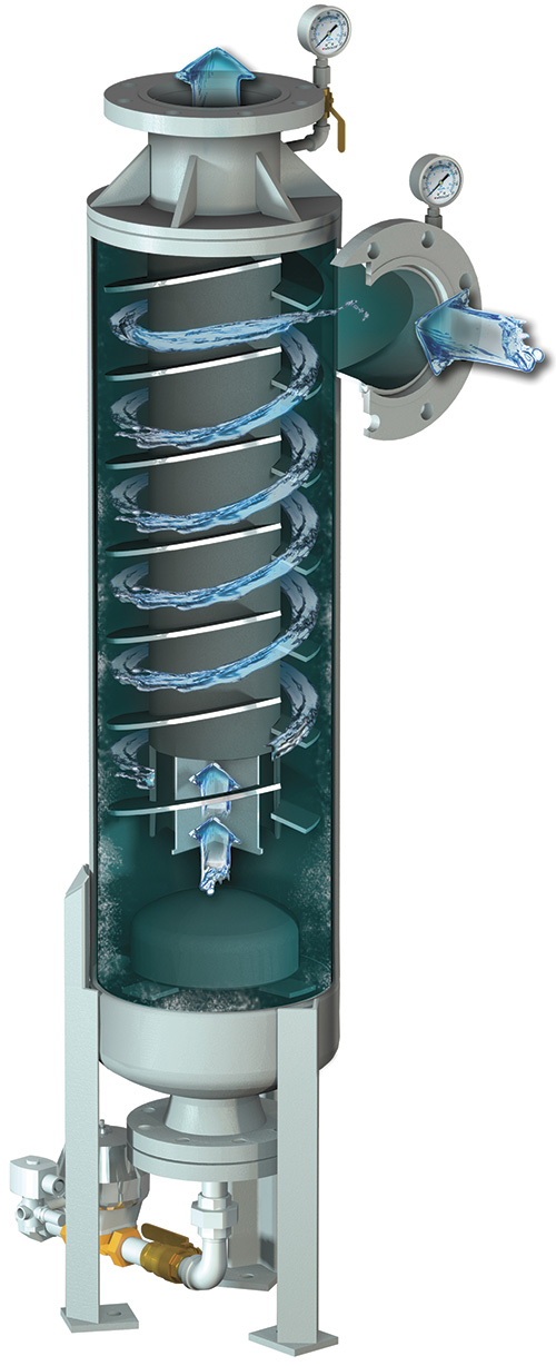 Image 4. A centrifugal solids separator (Courtesy of Fluid Cooling Systems)