Vertical diffuser vane pumps are crucial for high-pressure, high-capacity applications across various industries, including irrigation, flood control, fire protection and power generation. These pumps transport fluids vertically through one or more stages (or bowls), using a diffuser to convert kinetic energy into pressure energy (Image 1).
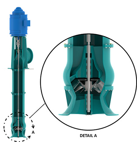
During operation, the impeller directs the fluid into multiple passages formed by diffuser vanes that are evenly spaced around it. Each passage typically expands in a cross-sectional area as the fluid moves from the impeller toward the pump column or discharge head. This design enables efficient fluid handling for high-capacity or high-pressure applications across multiple stages, though it also introduces specific design challenges.
This article explores the essential design factors for vertical diffuser vane pumps operating within a specific speed range (Ns = 1,500 to 13,000 [ns = 30 to 250]). It covers hydraulic requirements, impeller and diffuser design considerations, mechanical design aspects and hydraulic loads, emphasizing key elements that influence design choices based on specific speed.

When designing vertical diffuser vane pumps, efficiency is an essential parameter that needs to be considered. It is affected by various factors such as pump type, size, orientation and operating speed. One important factor that affects pump efficiency is the specific speed of the pump. Specific speed (Ns) is a parameter used to describe the performance of a rotodynamic pump. It is defined as an index of pump performance at the pump’s best efficiency point (BEP) rate of flow and total head per stage, with the maximum diameter impeller and at a given rotative speed (Equation 1).
ns (or Ns)=(n∙(Q)0.5)/(H)0.75
Where:
ns = specific speed in metric units
Ns = specific speed in U.S. units
n = rotative speed, in rotations per minute
Q = total pump flow rate, in cubic meters per second (U.S.
gallons per minute)
H = head per stage, in meters (feet)
Equation 1: Rotodynamic pump specific speed equation
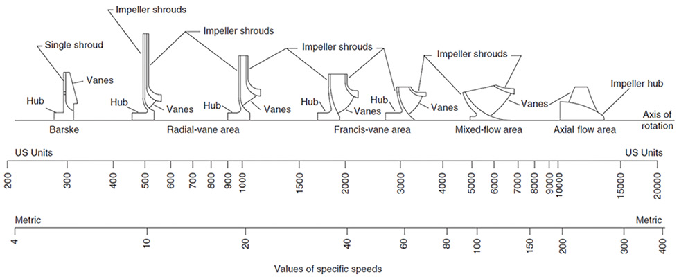
The index informs the design engineer of the optimal type of impeller required for the design (Image 2). Along with the impeller type, the specific speed will establish the maximum attainable efficiency achievable for the particular design. The attainable efficiency of a pump is the maximum efficiency that can be achieved for a given pump design based on pump type, design (BEP) flow rate and the specific speed. There are additional factors that can affect the attainable efficiency, such as surface finish of flow passages and the running or wear ring clearances of the pump’s internal components; however, their effect on maximum attainable efficiency is dependent on the specific speed of the pump. Higher output capacity pumps at BEP typically have a greater attainable efficiency than lower capacity pumps when designed for similar specific speeds, and understanding this relationship is crucial in the design process.
Before beginning the hydraulic design, the full scope of work should be clearly defined. This includes, but is not limited to, the minimum requirements for design flow rate, total bowl head, maximum number of stages, impeller type (enclosed, semi-open or open) and net positive suction head required (NPSHr) or available (NPSHa). Secondary factors, such as liquid type, viscosity range and specific gravity, should also be considered. In many cases, the required rotational speed is a key design factor and, when relevant, the impeller exit tip speed (peripheral velocity) should be calculated. When the exit tip speed exceeds 90 feet per second (27.4 meters per second), excessive noise and cavitation may occur, particularly when operating away from BEP. A general guideline (Dicmus, 1987) is to design for an exit tip speed below 90 feet per second (27.4 meters per second) and ensure the maximum rotational speed keeps the tip speed under 100 feet per second (30.5 meters per second).
Hydraulic design, unless scaling a pump to a different size with the same specific speed, is typically an iterative process involving trial and error. Initial calculations are often approximate and are refined as the design progresses. Since there is no standardized hydraulic design process for vertical diffuser vane pumps within the pump industry, detailed coverage of the process is omitted. However, several universally accepted factors guide the hydraulic design of these pumps, and understanding their importance is essential for both design engineers and end users.
Vertical diffuser vane pumps can be single stage or multistage pumps. They function by having an impeller impart velocity to the fluid, which is then converted into pressure energy by the surrounding diffuser vanes. The impeller rotates to increase the fluid’s kinetic energy, while the stationary diffuser vanes collect the fluid and convert its kinetic energy into pressure.
Impeller Considerations
The design of the impeller is critical to a pump’s overall performance. Like other aspects of pump engineering, it is an iterative process involving continuous refinement through analysis. The impeller must be tailored to meet the pump’s specific flow rate and head requirements. Key factors such as impeller type, size and vane shape significantly affect hydraulic efficiency. Vertical diffuser vane pumps can accommodate a variety of impeller designs—enclosed, semi-open or open—ranging from modified radial (Francis vane) to mixed-flow and axial-flow configurations (Image 3).
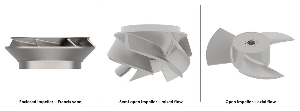
For vertical diffuser vane pumps operating at lower specific speeds, typically between Ns = 1,500 and 4,500 (ns = 30 and 90), modified radial impellers (commonly known as Francis vane impellers) are often used to minimize hydraulic losses, maximize energy transfer and reduce shock losses. The number of vanes is also critical to a pump’s efficiency and smooth operation: too few vanes may cause turbulence, while too many can lead to increased frictional losses.
Mixed-flow impellers, with specific speeds between Ns = 4,500 and 10,000 (ns = 90 and 190), are more complex and are often designed using the “error triangle” method. This process involves two main stages: first, selecting appropriate velocity and vane angles to achieve the desired performance; and second, laying out the impeller based on these angles and corresponding cross-sectional areas (Stepanoff, 1957). Several iterations are possible for any given design, each yielding variations in hydraulic performance.
Axial flow impellers, with specific speeds of Ns = 10,000 (ns = 190) or higher, follow a similar design process to modified radial (Francis vane) impellers. However, it is essential to consider the head range required to accommodate future applications, particularly under challenging suction conditions. The number of impeller vanes is determined by the specific speed. Often, four vanes are used for Ns = 10,000, three vanes for Ns = 13,000 and two vanes for specific speeds above 15,000 (Stepanoff, 1957). The hub ratio and vane spacing are also influenced by the specific speed. The typical vane pitch angle ranges from 12 to 22 degrees, and the vane thickness should be minimized to maintain mechanical strength while adhering to casting practices.
Vaned Diffuser Considerations
Diffuser vanes play a critical role in converting kinetic energy into pressure energy in a pump (Image 4). Their design must ensure a smooth transition of fluid from the impeller to the column pipe or next stage impeller, minimizing turbulence and flow separation.
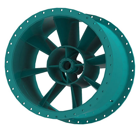
Key design aspects include vane angles, lengths and the spacing between the vanes, all of which should be optimized to reduce friction losses and avoid mechanical interference. The relationship between the impeller and diffuser, as well as the shape of the waterway immediately following the diffuser, are crucial components of the overall design. The exit of the diffuser can be tailored to meet downstream requirements.
The initial selection of diffuser vanes is often arbitrary, as the design process is iterative, involving trial and error. Typically, the number of diffuser vanes ranges from four in small axial flow pumps to as many as nine in large, low-specific-speed vertical turbines. In all cases, the vanes should be kept reasonably sharp and thin. It is common practice to design the diffuser with one more vane than the impeller, as using the same number of vanes can cause potential pulsation issues.
The length of the diffuser vanes should be based on the passageway length to ensure efficient diffusion and energy conversion. If the vanes are too short, energy conversion may be incomplete, resulting in reduced efficiency. The area between the vanes should increase progressively from the inlet to the outlet of the diffuser, with the area remaining relatively constant over the final third of the vane length. This design allows the fluid to smoothly transition either into the next-stage impeller or into the discharge column.
Mechanical Considerations
Managing axial and radial thrust loads is essential for ensuring mechanical reliability and longevity. Axial thrust arises from pressure differences across the impeller stages and the static weight of the impeller and shaft and must be carefully managed to avoid bearing failure or impeller damage. Techniques such as back wear rings with balancing holes or balance discs can help mitigate axial loads. Radial thrust, which is typically low due to the bowl diffusers equalizing the pressure forces, resulting from imbalanced fluid flow, can be reduced with proper alignment and well-designed diffuser vane geometries. Thrust bearings must be designed to handle the axial loads generated by the pump and the weight of the rotor.
The Hydraulic Institute follows American National Standards Institute (ANSI)/American Water Works Association (AWWA) E103-21 for designing vertical lineshafts. This standard specifies that the maximum combined shear stress on pump shafting should not exceed 30% of the material’s yield tensile strength (YTS) or 18% of the ultimate tensile strength (UTS). For threaded shaft couplings, the maximum shear stress is limited to 20% of YTS or 12% of UTS.
Shaft stretch is a critical factor in the design of vertically suspended pumps, particularly with semi-open impellers and deep-setting designs. The shaft elongates under axial downthrust, and proper impeller positioning is required to avoid damage. In long or deep-setting pumps, shaft stretch might exceed the available clearance, necessitating special machining or increased shaft diameter.
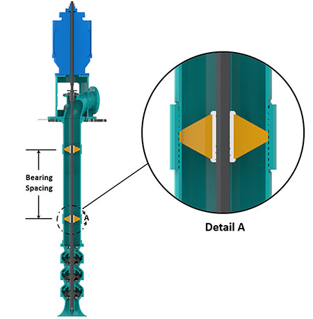
When calculating dry critical speed for lineshafts, it is crucial to consider lateral vibrations. Bearings are typically spaced no more than 10 feet apart (3.0 meters), with practical experience showing that water-lubricated rubber bearing bushings can operate successfully at 1,800 rotations per minute (rpm) with minimal vibrations (Image 5). For higher speeds, such as 3,000 or 3,600 rpm, bearing spacing should be minimized.
In vertical pumps, solid-shaft configurations use either rigid or flexible couplings. Rigid couplings are preferred for handling axial thrust through the motor bearings and can be adjusted to facilitate the axial setting. Flexible couplings, on the other hand, are used with separate thrust bearings. Hollow-shaft motors allow for axial adjustments and compensation for manufacturing tolerances and thermal effects. Coupling requirements depend on the shaft and bearing configurations: rigid couplings are used in applications with significant axial thrust, while flexible couplings are employed in others.
Lineshaft bearings support the shaft between the hydraulic end and the upper support plate or discharge head. In normal operation, these bearings experience minimal radial loads, but loads can increase in the pump bowl area. Proper design and concentricities are required to manage unintended loads and ensure bearing clearances.
Vertical diffuser vane pumps are essential for high-pressure, high-capacity applications, offering efficient fluid handling across multiple industries. Key design elements like the impeller, vane configuration and diffuser geometry must be carefully analyzed to meet specific performance requirements. Proper management of axial thrust, along with shaft alignment and bearing support, is critical for mechanical reliability and pump longevity. The design process is iterative, aiming to optimize efficiency, minimize noise and vibration, prevent cavitation and ensure a safe, reliable system.
For additional information on rotodynamic pump design and general attainable pump efficiency, readers are encouraged to consult standards such as ANSI/HI 14.3-2019 Rotodynamic Pumps for Design and Application and HI 20.3-2020 Rotodynamic Pump Efficiency Prediction, along with authoritative texts on pump design.
References
Dicmas, John L. Vertical Turbine, Mixed Flow, and Propeller Pumps. New York: McGraw-Hill, 1987.
Stepanoff, Alexey J. Centrifugal and Axial Flow Pumps: Theory, Design, and Application. 2nd ed. New York: Wiley, 1957.

