Focusing on vibration and dynamics issues during the plant design phase of a project often pays off with smoother commissioning and lower cost of ownership over the plant’s life. Occasionally, upon startup, new or modified pump systems suffer from reliability issues. Excessive vibration leads to premature seal and bearing failure, piping fatigue or catastrophic failures that lead to plant inoperability. Correcting a vibration problem when trying to commission a new or modified pump system that is already installed, instead of during the design phase, greatly increases project costs and can create costly schedule delays.
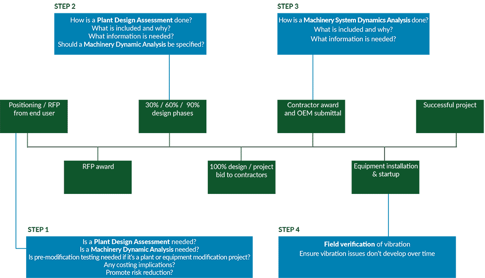
As highlighted in the lower left box of Image 1, the time to consider a vibration risk reduction effort is when engineering firms or contractors are preparing their response to a request for proposal (RFP).
The following summarizes typical risk reduction tasks typically performed by an independent vibration consulting firm:
- Plant design assessment during the 30% to 90% design phase of a new plant, modification or plant restart (this effort may include premodification performance and/or mechanical testing in the case of a plant machinery modification or restart)
- Preinstallation pump system dynamics analysis shortly after the pumps are purchased
- Post-installation vibration verification testing before the plant is turned over to the plant owner
Plant Design Assessment
Step 1 involves evaluating whether or not a more specialized vibration risk reduction effort is required (lower left box in Image 1). At the Step 1 RFP stage, the bidding engineering firm and/or contractor need to base their proposed risk reduction plans on their experience and knowledge about the plant owner’s aversion to vibration problems.
In many cases, a plant owner has been through the cost and schedule impacts of a significant vibration issue and will appreciate, or require, a proposal that includes a risk reduction plan. In other cases, the plant ownership group is still waiting to encounter such a problem and may not appreciate the need for risk reduction. Other system-related factors to consider include:
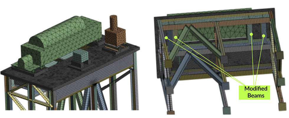
- Equipment mounted on elevated structures/upper floors of a building (as shown in Image 2)
- Long runs of vertical/horizontal pipe or column
- Tall mounting piers for rotating machinery (e.g., centrifuges on pedestals)
- Machinery system designs without an installation history
- Future flow requirements (or usage of staged installations)
- High energy or high horsepower equipment
- Length of shutdown in the case of plant restarts and machinery system condition when shutdown
In the case of a plant system modification or retrofit scenario, Step 1 includes consideration of the presence, or lack of, premodification testing. The advantage with plant modifications is that there is equipment to physically test (equipment does not necessarily need to be operational to test). The resultant specialized test data can be used to:
- Identify additional issues that need to be addressed during the actual plant system retrofit work to help ensure
smooth commissioning (soft foot or baseplate delamination, for example) - Establish the current vibration amplitude values and system natural frequencies, including damping information
- Help improve the accuracy of Step 2 and Step 3 analyses by calibrating “as built” system finite element analysis (FEA) models with actual test data
It should also be determined during Step 1 if the specifications should require a pump (or machinery-specific) system dynamics analysis (Step 3), and post-installation field testing (Step 4) to reduce the risk of vibration issues during plant/equipment startup. ANSI/Hydraulic Institute Guideline 9.6.8 provides a quantitative methodology that considers both risk and uncertainty to determine if, and what level of, analysis is needed for the pump dynamics analysis (upper right box in Image 1). It also provides guidance for specification writers with sample specifications.
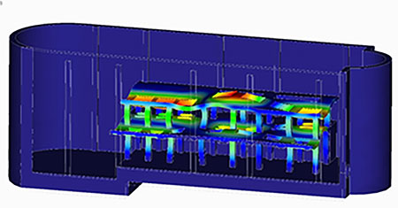
Step 2 (plant design assessment) is initiated with the pump system vibration specialist company consulting with the engineering firm (upper left box in Image 1). Modern FEA methods can also be utilized using notional pump system designs during the 30% to 90% design phases. Image 3 shows an example of FEA dynamic analysis results for a plant design at the 60% design phase.
A key outcome of Step 2 is verification that the system foundation and piping are properly designed from a pump dynamics standpoint. If any issues are noted, such as a structural natural frequency in the system, the foundation and piping can be redesigned to avoid this issue well before concrete is ever poured.

Pump System Dynamic Analysis
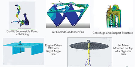
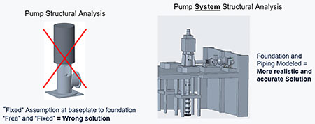
Step 3 is a more detailed analysis of the “final” equipment, structure and piping designs. This is the final check before manufacturing of the equipment to ensure there are no lateral or torsional natural frequencies (internal to the pump being purchased) or structural natural frequencies (a system issue involving the pump, foundation or piping system) before manufacturing. In all cases, the assessment and test methods used to analyze, characterize and finalize the structural dynamics of a pump system need to be considered beyond just the pump (Images 4 and 5). The pump system includes the support structure and floor, portions of the building, nearby piping and operational effects such as water level and multi-machine operation.
Piping acoustics can also affect system dynamics, and are sometimes considered. By not including all of the relevant system information, poor assumptions of the structural dynamics will be made. One case study showed a 32% difference in structural natural frequency based on poor assumptions. Typical safety margins for these analyses are only half or less of a 32% error. FEA methods are frequently blamed for inaccurate results when the culprit is operator error (for example, bad assumptions due to a lack of system understanding).
Furthermore, there are industry standards, guidelines and criteria to help specification writers reduce the risk of encountering such damage-causing vibration issues. Industry standards and guidelines include those from the International Organization for Standardization (ISO) 10816, ANSI/Hydraulic Institute and the American Petroleum Institute (API).
Post-Installation Vibration Verification Testing
Step 4 (lower right portion of Image 1) notes post-installation vibration verification testing near the end of the plant system design process. One goal of field vibration verification testing is obvious—to confirm that the pump system meets overall vibration criteria as originally set forth in the specification. Pump testing and vibration criteria are provided in industry standards and guidelines such as ANSI/Hydraulic Institute Standard 9.6.4, ISO 10816 or API 610. Engineering firms and some end users will also have their own specified vibration requirements.
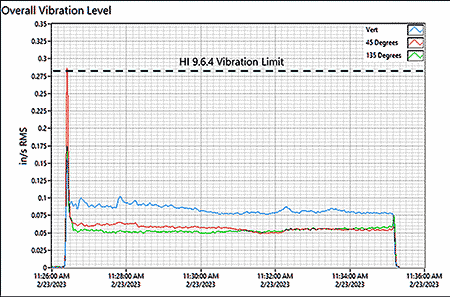
Image 6 is an example deliverable from a vibration acceptance test if the test is properly specified. It shows overall vibration levels at one measurement location in three directions while the pump operates within its acceptable operating region. There will be several measurement locations specified and several speed lines in the case of variable speed equipment.
The specifications should also require that the independent test company provide and analyze fast Fourier transform (FFT) vibration plots (or vibration signatures), which show vibration amplitudes versus vibration frequency. Potential issues such as misalignment or imbalance can be identified and corrected before the new or modified plant is turned over to the owner. The time and cost adder is nominal, and an FFT analysis provides excellent value for reducing vibration risk.
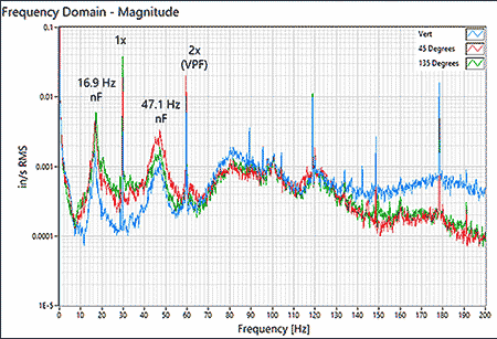
Image 7 is an example of a delivered FFT with key excitation sources (running speed and vane pass frequency) compared to natural frequencies. Problems such as imbalance, misalignment and internal rubbing can be identified and eliminated based on the FFT.
If properly specified, the verification test can result in more reliable pump system operation and reduced operating costs over the life of the plant. If lowering the overall cost of ownership is an objective, an experimental modal analysis (impact test) should also be properly specified. Impact test results can allow an experienced pump engineer to predict the future while helping to ensure the pump system will operate over the life of the plant without encountering resonant vibration. Image 8 is a key deliverable from an impact test. It is a frequency response function (FRF) plot, which helps to show the natural frequencies, or vibration modes, of the pump system.
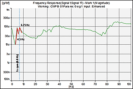
FRF plots are evaluated to:
- Confirm that rotating machinery and related piping is not suffering from a structural resonance issue
- Confirm that the specified separation margins between excitation frequencies, such as running speed, and natural frequencies (usually 15%) have been met
- Evaluate the potential for encountering a damage-causing resonance issue as the pump system ages (if there is not enough separation margin, it is more likely the pump system will have excessive vibration at some point over the life of the plant)
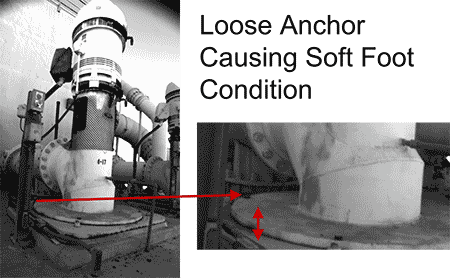
An emerging verification test is the use of motion magnification video (MMV), sometimes referred to as video vibration amplification, as seen in Image 9. This fairly new technology and product was originally used primarily for troubleshooting. High-speed cameras and specialized software exaggerate and slow down the system’s motion so potential dynamic problems can be seen in the video and corrected. Displacements as low as 0.1 mil peak-peak (pk-pk) with a 10-foot field of view can be identified.
All vibration data collected during the verification test can be also used as a baseline or birth certificate for comparison to later data (trending) if a plant is practicing predictive maintenance to lower the cost of ownership.
Specifying and implementing the analysis and testing methods as discussed in this article can reduce the risk of vibration issues for the plant owner, contractor, engineering firm and manufacturers. Over the long term, it will also lower the overall cost of ownership for the plant owner.

