Methods for pressurized seal systems
John Crane
03/06/2019
There are many methods to pressurize the barrier fluid for a dual pressurized mechanical seal. Each method, or piping plan, uses a different mechanism to apply the pressure to the barrier fluid and, as a result, each has its own set of advantages. One of these methods is American Petroleum Institute (API) Plan 53C. Although not as widely installed as a traditional API Plan 53A system, it does differentiate itself from other methods. API Plan 53C has the ability to change the barrier pressure as the pressure inside the pump changes.
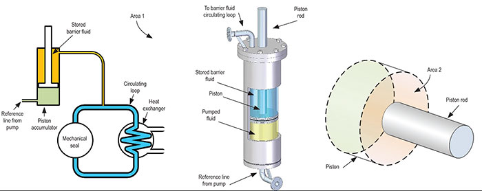 Image 1 (left). Simplified Plan 53C schematic. Image 2 (center). Typical piston accumulator. Image 3 (right). Piston face areas. (Images courtesy of FSA)
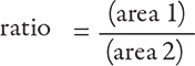 Increasing the piston rod diameter has the effect of reducing Area 2, and thus increases the pressure amplification ratio.
Due to the practicalities of design and function, amplification ratios are typically in the range of 1.05 to 1.30. Pressure ratios above this have large diameter piston rods (relative to the cylinder) and become longer in order to provide sufficient barrier fluid storage volume.
Increasing the piston rod diameter has the effect of reducing Area 2, and thus increases the pressure amplification ratio.
Due to the practicalities of design and function, amplification ratios are typically in the range of 1.05 to 1.30. Pressure ratios above this have large diameter piston rods (relative to the cylinder) and become longer in order to provide sufficient barrier fluid storage volume.
Tracking the Barrier Pressure
As the pressure changes in the reference line, the pressure produced by the piston accumulator and delivered to the barrier fluid circulating loop will change proportionally to the amplification ratio.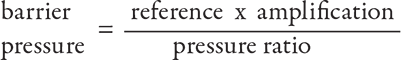 The ability to track barrier pressure with respect to the reference pressure is what makes an API Plan 53C different from other dual seal barrier systems. Since the barrier pressure is generated by amplifying the reference pressure from the pump, the piston accumulator requires no external utilities to function, which further simplifies the installation and operation of a Plan 53C system.
Pump Reference Pressure & Amplification Ratio Selection
Selecting the right amplification ratio and reference pressure point on the pump pressure casing is key to ensuring the correct barrier pressure for the mechanical seal. API 682 recommends a minimum barrier pressure of 1.4 bar/20 pounds per square inch (psi) above the seal chamber. The reference pressure and the amplification ratio need to be selected to meet this minimum requirement. Additionally, the range of pressure at the reference point must also be factored into the selection process. For high pressure pumps, the seal chamber can be used as a reference pressure and meet the minimum differential pressure requirements. A simple connection in the seal chamber or mechanical seal gland plate can be used to plumb a reference line to the piston accumulator. However, for low pressure pumps, a pressure higher than the seal chamber must be maintained in order to meet the minimum differential pressure requirements. Depending on the pump design, this can be the pump’s final discharge pressure or the discharge of an intermediate stage (if the pump is a multistage design). An alternative design would be a piston accumulator with a “helper spring” that provides a minimum pressure offset.Installation & Commissioning
The two elements of the Plan 53C system, the barrier fluid circulating loop (with heat exchanger) as well as the piston accumulator, need to address different factors. The barrier fluid circulating loop needs to be installed to offer the least resistance to barrier fluid flow produced by the pumping ring located within the mechanical seal.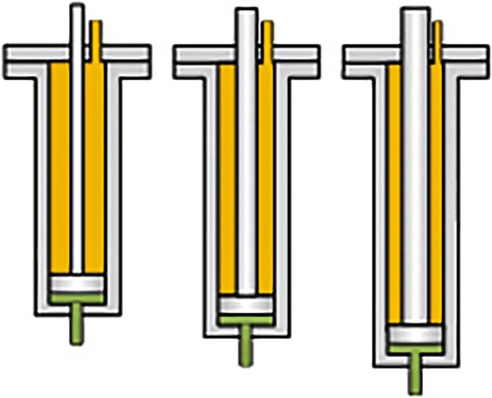 Image 4. Length increase with amplification ratio and constant stored barrier fluid volume
Piston Accumulator Operation
During operation, barrier fluid is consumed due to normal leakage of the mechanical seal. Barrier fluid stored in the piston accumulator moves into the barrier fluid circulating loop to replace the lost barrier fluid, resulting in the piston and piston rod slowly moving upwards. The extension of the piston rod from the top of the accumulator provides a direct indication of the volume of barrier fluid remaining in the accumulator. A scale can be mounted to a bracket adjacent to the piston rod to provide a local display of the remaining barrier fluid. Proximity switches can also be fitted at desired alarm points to provide a remote indication that minimum volume threshold points have been exceeded, or a linear position transmitter can be installed to provide a precise remote indication of the barrier fluid remaining. A shield is recommended to prevent accidental damage and the effects of dirt and debris from weathering to the surface of the piston rod and piston rod seal. Periodically, the consumed barrier fluid will need to be replenished. This is achieved by pumping barrier fluid from a reservoir into the piston accumulator. Typically, a wheeled cart with a small reservoir and pneumatic or hand pump is used to replenish the barrier fluid. The replenishment interval is determined by the size of the piston accumulator and the rate of normal barrier fluid consumption of the mechanical seal.Plan 53C Limitation
The pumped media is used as the source of pressure in the piston accumulator. So, the properties of this pumped fluid must be considered when selecting a Plan 53C system. The following pumped fluids should be avoided to ensure reliable operation of the barrier system:- Pumped fluids that solidify at ambient conditions. As there is effectively minimal flow of fluid in the reference line, the fluid in this line will, over time, cool down to ambient temperatures. Fluids that solidify as they cool can plug the reference line preventing the pump pressure from acting against the piston in the accumulator and resulting in loss of barrier pressure.
- Pumped fluids that contain suspended solids. The suspended solids can migrate into the piston accumulator and interfere with the function of the piston seal, causing wear and damage to the internal surfaces of the cylinder resulting in leakage past the piston seal and loss of barrier fluid.
- Pumped fluids at elevated temperatures. As the pumped fluid is introduced into the piston accumulator during commissioning, thermal damage to the piston seal can occur if it is exposed to temperatures above the limits of piston seal material(s).
- Pumped fluids that are corrosive. The compatibility of the materials of construction of the piston accumulator with the pumped fluid should be reviewed to ensure no corrosive damage occurs to the internal walls of the accumulator and to the piston seals.