HALLE, Germany (Aug. 22, 2013) – The problem is big.
An average of 39 million tons of sewage flow each year from the 35 most polluted combined sewer overflows (CSOs) in London—currently part of a 150-year-old Victorian network that can no longer accommodate the excess sewage and rainwater.
The challenges to solve the problem are even bigger—a pump station buried 85 meters below the surface in a shaft 32 meters in diameter.
At the heart of the solution are big pumps—54-ton Super Pumps specifically created by KSB to operate within a complex, carefully-engineered pumping system.
“This is the biggest wastewater pump that KSB has ever built,” said Maik Ulmschneider, head of KSB’s Waste Water Competency Center. “The whole project is superlative—the magnitude of the project itself, the size of the tunnel, the size of the pump, the size of the motor and the size of the test rig. The size makes it a challenge. Other than that, everything is normal. This is critical, innovative wastewater pump engineering, which is what KSB does best.”
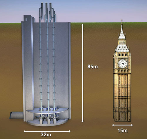 Image 1. The Lee Tunnel pumping station shaft is as deep as Big Ben is tall.
The 7.6 kilometer (km) Lee Tunnel is the first of two tunnels designed to capture and redirect about 16 million tons of stormwater and sewage as part of the proposed 25-km Thames Tideway Scheme. It will run beneath the River Thames through Central London.
The depth of the shaft is equal to the height of Big Ben (see Image 1). The pumping station will operate below the Beckton Sewage Treatment Works, Britain’s largest wastewater and sewage treatment plant.
“This is the biggest water/wastewater infrastructure project in this decade in Europe,” Ulmschneider said. “Being part of this project is a big reference for us. We have gone above and beyond to find just the right customized solution that will make our customer happy.”
The investment for Thames Water is also big. The price tag of 2 billion pounds sterling for the entire Thames Tideway Scheme makes this the most expensive water project ever undertaken in the U.K.
KSB is providing the first four of the six single-stage, end-suction Super Pumps required to get the job done. It will also supply two smaller, but powerful, drainage pumps.
Each KSB SVP-84 Super Pump (cast and manufactured by GIW Industries in Grovetown, Ga.) will run in a working range between 3,050 liters per second (l/s)/87.1 meters of head (2.9 million gallons per hour (gph)/48,343 gallons per minute (gpm) and 1,950 l/s/16.89 meters of head (1.85 million gph/30,908 gpm).
The pumps feature impellers measuring 2.2 meters in diameter. Each wear-resistant, white cast-iron pump is powered by a Siemens A-modyn vertical motor, which runs at 3.4 megawatts (MW) at 6,600 volts/50 hertz and speeds up to 333 rpm (see “Powering the Pumps”).
To keep the motors cool, KSB designed heat exchangers specially engineered for this underground application. Compared with equivalent air-cooled systems, these heat exchangers will sharply reduce the amount of energy required to dissipate the thermal load.
“The biggest challenge in deep tunnel installations is getting as independent from the outside as you can,” Ulmschneider said. “Once any piece of equipment is hooked to the crane, it takes 20 minutes just to get it to the bottom of the tunnel. When you need to install several pieces, it can take a week to just get the equipment down there, and that doesn’t count the time needed to install it. The whole installation process in the shaft is a story in itself. The pump has to be installed inside the station. It is a very tight space. And of course, you can’t just call a guy and say, ‘I need help moving this 54-ton pump.’ It involves big, expensive equipment, a lot of people and a lot of time.”
 KSB Halle's testing facility for the super pump. Click to enlarge.
Experience Solves Challenges
KSB has a history of successful applications in supplying equipment to similar scale projects in Russia, the U.S. and Mexico (see Pumps & Systems, March 2012 article “Wastewater Pump Stations Relieve Flooding”). This experience was essential in the company’s award of the contract.
“Deep installations come with many obvious challenges and other challenges that are found in the details during the design stages,” Ulmschneider said.
“We see a trend now that more big cities are using deep tunnels. One reason is increased awareness of the environment, so they think about CSO solutions. These solutions involve deep tunnels because all the other space in the ground is already occupied by metro, gas, normal sewage systems—all kinds of existing infrastructure.”
For the URS-422 project in St. Petersburg, Russia, KSB used smaller, dry-installed submersible pumps at a depth of 92 meters, Ulmschneider said. The best solution for this particular project was more pumps—12 of them—but the flow capacity of each pump was lower. “Because of this deep tunnel trend, we developed a complete range of pumps for both pure dry installation or dry-installed submersibles,” Ulmschneider said. “We expanded our existing range to meet the requirements of the trend.”
Each deep tunnel project requires a fully customized solution.
“During the early stages, the client often needs help defining solutions for their particular project,” Ulmschneider said. “We can customize the project to meet specific needs. KSB is the only company that has this kind of variety, which is an advantage for us. Every owner, every utility and every location has different requirements and challenges, so this range is critical. A company will invest billions into a project like this, and the pumps have to work.”
Building the Lee Tunnel Super Pumps
In 2011, GIW Industries received an order from KSB, its parent company, to build the four massive pumps for the Lee Tunnel project. Because the scope of this project forced the pumps to be large, it played into GIW’s strength, according to Bob Visintainer, GIW’s VP of Engineering.
GIW builds huge pumps for the mining industry and manufactures large castings. Some of the existing hydraulics were already in place, thanks to the LSA-84 dredge pump that was built by GIW in 1987. This was used as the flagship design for the Super Pump.
“We were challenged with building these hydraulics into a vertical configuration,” Visintainer said. “GIW designed the mechanical end and the vertical configuration. The wet end parts are similar to pumps we have built before, so there were no surprises there.”
The design process took about 16 months with a team of 15 engineers and CAD operators, Visintainer said. For this project, there were two engineering teams—one on the mechanical side and one on the pumping side.
“This project is important for a number of reasons,” Visintainer said. “The pumps alone are a multi-million dollar order. The government of the capital city of an important European country supports the project, which makes it high-visibility. A lot of people are watching it closely. The issue of stormwater storage is a big one for many cities.”
The mechanical seal is complicated and was specially made for this pump by EagleBurgmann design engineers Hans Steigenberger and Peter Haselbacher. The Lee River HGH 300S1/400-E1 seals have split seal faces, which can be replaced without tearing down the pump. The seal weighs 300 kilograms with a shaft underseal that measures 279 millimeters (11 inches) in diameter (see “Mechanical Seal Technology”).
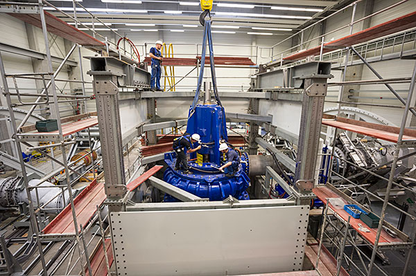 Image 2. Disassembly of Super Pump No. 2 after hydraulic performance testing. Photo courtesy of KSB
“Once these pumps go down into the pit, anything that has to be done to them will become very complicated,” Visintainer said.
“Our focus is on reliability. We have to consider what could potentially go wrong. We worked with the designers at EagleBurgmann to go through every possible scenario so that we would have the best chance of a flawless operation.”
Testing, Part One—Rag Monsters
In wastewater pumping, the easiest thing to pump is water. The hardest thing to pump is rags, Ulmschneider said.
“Wastewater pumping is unpredictable,” he explained. “You never know what you are going to get. When it comes to rags, no one knows how they will behave because there is no data of record for testing rags with a pump of this size.” The rag tests were the most groundbreaking tests performed on the Lee Tunnel Super Pumps. These tests established a basis for all future wastewater pumping.
“Thames Water wanted to be sure to minimize the potential for blockage,” Visintainer said. “This whole system depends on these four pumps running properly, so this test became one of our most critical steps in the entire process.”
For the rag testing, the passing requirements were specific: 2 kilograms dry weight of rags per cubic meter to a maximum length of 1 meter must be pumped for six hours at three different duty points without clogging the pump.
The rag tests were performed at GIW’s Grovetown facility and lasted four months (November 2012 – February 2013).
“We discovered quickly in the test lab that the liquid was recirculating at 350 rpm once every 15 to 30 seconds. In one hour, every rag was going through 100 to 200 times,” Visintainer said. “The fibers of the rags began to tangle and form what we called ‘rag monsters.’ These were clumps bigger than two grown men (nearly 5 meters), which created blockages within 30 minutes (see Image 3).”
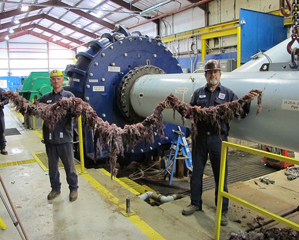 Image 3. One of the "rag monsters" generated by the historic four-month rag testing. Photo courtesy of GIW Industries.
KSB and GIW fulfilled the customer’s requirements, but they did not stop there. There was an opportunity for further internal scientific testing to learn what the pump could truly handle.
“We wanted to find out how rags behave in a closed system,” Ulmschneider said. “When do they clog the system? When does the pump start to fail? This test is groundbreaking, not only for KSB but for the wastewater industry as a whole. It is the first comprehensive rag test of this magnitude. We met the contractual requirements of the customer and then really pushed the pump to the edge. We discovered what it could do. We now know at what point the pump will begin to struggle and when it will shut down.”
Testing, Part Two—Performance Tests
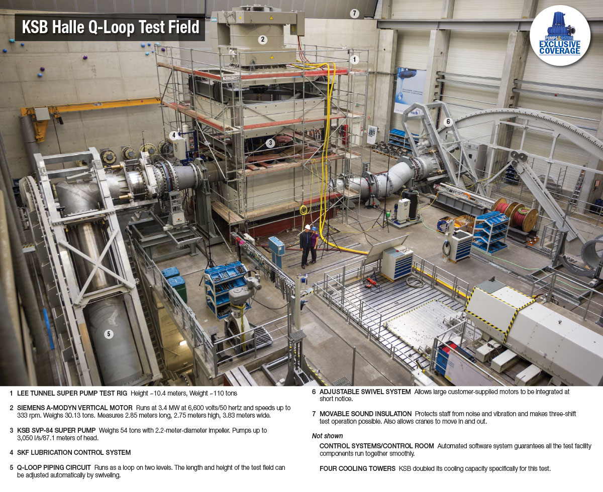
Complete hydraulic performance tests were performed on each of the four Super Pumps and each of the four motors at KSB Halle’s Q-Loop Test Field, one of six state-of-the-art test fields at this location. Performance testing included the pump running continuously at four different duty points for two hours, explained Dr. Thomas Hennig, KSB’s test field engineer. The maximum speed (critical point) is a flow rate of 3,000 l/s with total head of 87 meters. At this point, the pump should absorb the power of 3,000 kilowatts (3 MW).
The highest absorbed power ever tested at the Halle facility is 3.4 MW, Hennig said. This test field has the capability to test up to 10 MW.
It was a goal to come as close as possible to a real-life situation in the pumping station. The total height of the Lee Tunnel test rig is 10.4 meters, including the original carbon cardan shafts of 1.2 meters.
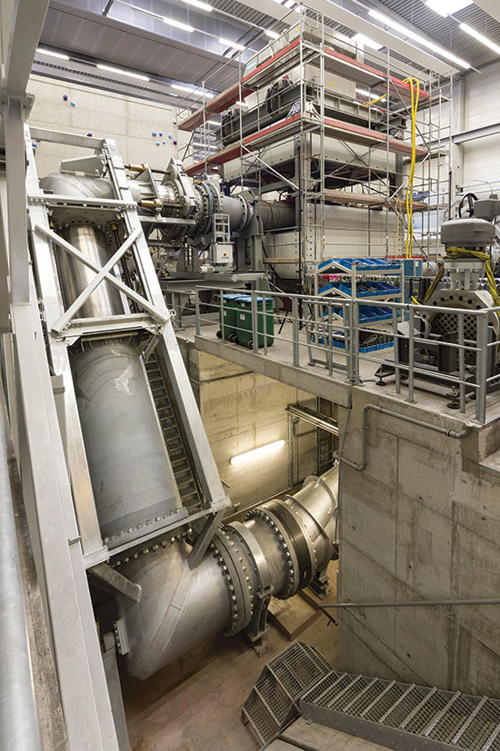 Image 4. The KSB test rig for the Super Pump hydraulic performance testing. Photo courtesy of KSB.
Another challenge was that the clear height on this test field was limited to just 10.6 meters because of the maximum height of the cranes. Only 203 mm (8 inches) were available to maneuver, which is not a lot of space when it comes to moving such heavy equipment (see Image 4).
Each test lasted about five hours and required an additional cooling system, which KSB was prepared to handle.
“Within KSB, we have several test fields all over the world,” Ulmschneider said. “This test field in Halle is the only KSB test field that can allow for the electrical power, dimensions and functionality that can comply with all the testing requirements for this project. But even this test field needed extra cooling for the continuous two-hour test.”
KSB invested 18 million Euros in 2009 to build a testing facility that would accommodate pumps of this size. This included the test field, test field hall and XXL machining centers. Two cooling towers were built at that time, but space was made to accommodate six.
Two more cooling towers were added specifically for this project. “We doubled our cooling capacity to accommodate the long-term, two-hour permanent tests for this project.” Ulmschneider said. “When we built this test field, we made provisions—from cooling size and electrical power input size—that maybe we would need to test even larger pumps one day. Today, we don’t build many pumps that need 10 MW of power, but we are prepared for when we do.”
The first part of the performance tests involved two hours of continuous running at the specified 3,000 l/s. KSB measured the time gaps in 10-minute intervals. For the test to be successful, the average flow rate/total head should remain constant for two hours. The winding and bearing temperatures of the motor and bearing temperatures of the pump were measured. During the two hours, the temperatures rise. The temperature time test determines the estimate of the temperature values after a long period of constant running. Maximum limits were measured, not overloads.
The second part of the performance test measured one complete performance curve by changing the flow rates. This was measured four times at four different speeds: 326 rpm, 315 rpm, 166 rpm and 150 rpm. Four performance curves were determined. These tests also measured vibration, bearing temperatures and noises.
The final part of the testing involved measuring net positive suction head at a speed of 326 rpm.
“A performance test is normally a standard test of each pump, and we have a contract with the client for the guaranteed points,” Hennig said. “We give the client information about how the pump will run at these conditions. These tests show whether the specified tolerances can be fulfilled.”
The client was present to witness all the testing in every stage of the process.
Each of the four pumps could run differently. “We run it until we get it right,” Hennig said. “Sometimes, the pumps have to be adjusted or reworked to meet the client’s requirements.”
This test field includes a complete closed-loop system. Water travels through large tubes to reach the pump instead of other test fields that use open basins.
This Q-Loop Test Field runs approximately 100 tests per year and can test pumps with a capacity of up to 5,043 l/s with a maximum head of 600 meters.
Testing Coordination
Andrea Gros is an industrial engineer and is KSB’s head of production for large pumps. She was responsible for coordinating the schedule for the performance testing, a process that took a year and a team of five engineers to accomplish. Gros coordinated all the experts, designed the setup for testing, scheduled the six-week testing process, verified all the technical specifications and was the primary problem solver.
The most challenging aspects, she said, were the weight of the pump, the size of the pump, the electrical power needed and the vertical installation for a wastewater application. Every tool and accessory for the tests had to be specially designed.
Gros created a detailed schedule, which included a setup simulation to determine how long assembly and disassembly of the pump and test rig would take. The pumps were delivered in parts, and the setup had stages. The pump was assembled on the test field, and then the test rig support frame (tower) was built around the pump. After this, the impeller was installed. Then the bearing bracket was added, followed by the remainder of the tower and the motor.
“Engineers from KSB spent time at the GIW facility during the manufacturing of the pumps to understand exactly how the pump needed to be assembled and to identify how long it would take,” Gros explained.
Building the test rig for each pump requires five people working 16 hours per day for three days. “The environmental conditions of the test field were the most challenging,” Gros said. “The floor stands on springs. This is a special foundation to absorb any vibrations that could affect the other equipment. Also, calculations were made with the help of the University of Applied Sciences Merseburg, which helped determine how the testing would affect the piping system and other systems. It took two weeks to work that out. It was a flowing process. We had to just solve one problem at a time and then begin discussing the next one.”
Pumping Station Special Features
The pump station is divided into two parts and is prepared for three pumps on each side (see Image 5). In addition to the four Super Pumps and two drainage pumps, KSB also designed, fabricated and will install several ancillary features, according to Uwe Hilpmann, KSB’s project manager for the Lee Tunnel project.
KSB designed suction bends on movable devices, which glide about 9.7 meters and serve two purposes:
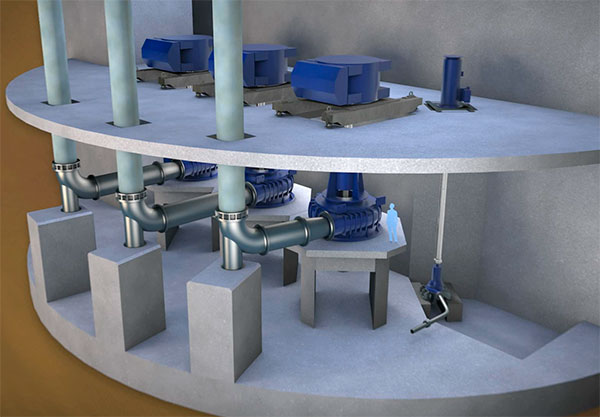 Image 5. An illustration of the Lee Tunnel pumping station
- They provide a connection from the suction bend to the tunnel and are used for access to the tunnel to investigate issues and fix problems.
- They provide access under the impeller.
A system, which was specially designed for this project by KSB, lubricates the bearings from a reservoir, Hilpmann said. The oil is sprayed directly onto the bearings inside the closed loop.
The Super Pumps are installed on the concrete level on a plinth (28.78 meters) and the motor is installed on the motor floor level above the pumps (35 meters). Two KSB Sewatec K 250-900 drainage pumps will be installed, one on each side of the pumping station. “If the Lee Tunnel is full of water, the water level would be about 85 meters,” Hilpmann explained. “Operating the main pumps lowers the water level by 33 meters, then they stop and the drain-down pumps take over.”
The actual flow rate of the drain-down pumps is 160 l/s (minimum) to 260,000 l/s (maximum) with actual developed head of 86.60 meters to 83.80 meters. The pump efficiency is 59.23 to 71.28 percent with 229.65 kilowatts to 299.93 kilowatts pump power absorbed. These pumps operate at 817 to 827 rpm.
Ready for Heavy Duty
Three of the world’s leading civil engineering contractors—Morgan Sindall, VINCI Construction Grands Projets and Bachy Soletanche (MVB)—are working with Thames Water to build the Lee Tunnel.
Construction began in 2010 and tunneling began in January 2011. Operation of the Lee Tunnel is expected to begin in 2016. The current target completion date for the entire Thames Tideway Scheme is 2023.
The first four pumps are expected to be installed in the third quarter of 2015. After one year of operation, KSB will disassemble and fully-inspect one of the pumps. The pumps will be maintained and serviced by the specialists from the Britain-based KSB Limited.
“These Super Pumps have been challenged a great deal during this project, and so have we,” Ulmschneider said. “Seeing these pumps being pushed to the edge and not fail gives us a lot of confidence for all the challenges to come. We are ready.”
Powering the Super Pumps
Pumping power of this magnitude requires a motor that is customized to handle extremely high temperatures and voltage. Each KSB Super Pump is powered by a Siemens A-modyn vertical motor, which runs at 3.4 MW at 6,600 volts/50 hertz and speeds up to 333 rpm.
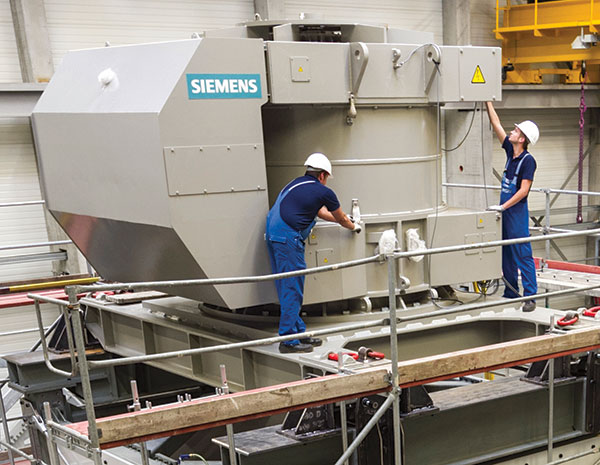
“Our challenge was to design a motor that could increase the power factor to 400 amps,” said Torsten Fiedler, Siemen’s sales manager for medium-voltage motors. “We added iron into the design to improve the power factor and the electronic behavior of the motor. This motor has a special electronic package. The stator of the motor consists of iron laminations. The more laminations in the design, the better the power factor and the lower the current.”
Each motor weighs 30.13 tons and measures 2.85 meters long, 2.75 meters high and 3.83 meters wide. The motor features a Rockwell Automation variable frequency drive.
One of the biggest challenges in creating the right motor to power the Super Pumps was the weight of the motor, Fiedler said. “Our competitor offered a motor that weighed 50 tons, but it was rejected by the client. Siemens was able to create a motor with the same power but with a lower weight.”
The Siemens design features a water-cooled motor. The motor has a constant air stream cooling circuit. The heat exchanger serves as the water cooler. Fresh water runs in between the motor casing and the cooling jacket. Water circulates and cools the inner parts. It is cooled by the rising pipe connected to the heat exchanger in the closed circuit. “This is a special design,” Fiedler said. “Usually, the water comes from an open source.”
These motors—manufactured at the Siemens Drasov, Czech Republic, facility—are a special design made for pump applications.
Mechanical Seal Technology
The mechanical seal is complicated and was specially made for this pump by EagleBurgmann design engineers Hans Steigenberger and Peter Haselbacher.
The Lee River HGH 300S1/400-E1 seals have split seal faces, which can be replaced without tearing down the pump (see Image 6). The shaft underseal is 279 mm (11 inches) in diameter. The seal weighs 300 kilograms.
Mechanical Seal Technology (continued)
EagleBurgmann and GIW worked together early in the project to carefully design the mechanical seal to meet the needs of the pump and also to account for the special challenges of the deep tunnel project.
“The seal for this project was specifically designed for purpose,” Haselbacher explained. “On the one hand, it is a simple semi-split case design—only it is much bigger. However, there are special issues with a vertical system. It must be straightforward and as safe as possible but engineered to purpose.”
In the HGH semi-split seal design, repairs can be made with the split parts. This is critical for this particular application, Haselbacher said. “Semi-split mechanical seals are used if there is sufficient axial clearance to pull off the seal housing and seat housing until the sliding parts are accessible. That is, only the wearing parts—such as the seal faces and O-rings—are split,” Haselbacher explained.
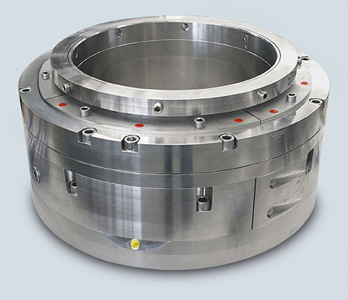 Image 6. The Lee River HGH 300S1/400E1 seal
“In the case of the GIW seal housing, Part 4 is made split, for the case of repair, as space is limited. The seal faces, O-rings and springs can be replaced without complete disassembly. In the case of the GIW pump, the inflatable seal has to be activated.”
Haselbacher explained that the mechanical seal for this project was designed with an inflatable seal that blows up “like a tire” 2 to 3 bars above product pressure to prevent leakage. This is a safety precaution. The pump cannot run with the seal inflated. “The flowback device is state-of-the-art,” Haselbacher said. “This helps keep the seal chamber free of particles.”
The seal usually has a flush in with clean water (plugged Bore 1 in Figure 1) with about 15 to 20 liters per minute. This is to keep the area around the seal as clean as possible since a bell-shaped seal chamber cannot be used in this application, Haselbacher said.
“In case of necessary repair by opening ‘the flush out’ for cleaning (Bore 2) so the service personnel can clean up the seal chamber before opening. We flush the seal chamber with clean water.”
The plugged bore (Bore 3 in Figure 1) is for venting.
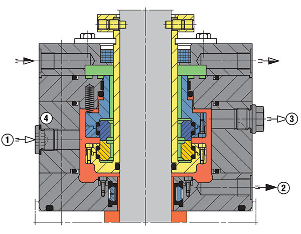 Figure 1. Spacial drawing of the Lee River HGH 300S1/400-E1 seal
“Venting will always occur before startup of the pump to assure that the room is free of air and gas,” Haselbacher said. “The pump is vertical, so dry running of SiC/SiC faces is often the reason for seal failure. With a seal like this, liquid at the faces must always be assured. The expectancy of the life of the seal is until total pump revision. The pressure-less quench (see the green areas in Figure 1) on the inside of the faces provides an additional backup.”
The two seal faces have a stationary design that can move from the top using springs to close the gap. This provides leakage protection if there is movement of the shaft, Haselbacher said.
Both seal faces are designed floating in between two O-rings. This is to allow for easy replacement in case of service and to uncouple the faces, Haselbacher said. The seal is serviced through the bearing bracket and disassembly is not needed to make repairs.
The maximum operating limits of the seal (depending on size, speed and pressure) are:
- Shaft diameter: 50…750 mm
- Pressure: 25 bar
- Temperature: 150 C
- Sliding speed: 20 meters per second

