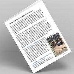
In the oil, gas and process industry, engineers and technicians must face the problem of maintaining a hermetic seal for a variety of industrial equipment. An example is flanges, which are the most common attachment method of one pipe to another pipe or equipment. Since the parts to be jointed are both rigid, they both must be perfectly machined and aligned. They also must maintain this aligned position during changing service conditions in order to maintain a seal. This can be difficult to achieve given the nature of alloys used in equipment, the fluids to be contained, as well as process variables (such as vibration, temperature variations, wear and chemical compatibility) and cost constraints (man-hour maintenance time, cost of products and downtimes).
This is why gaskets are crucial. A gasket is intended to fill the gap between two mating components, generally softer than the rigid parts to be joined, and to prevent the loss of fluid in the form of leakage. A seal is achieved by compressing the joined objects and the gasket, making the latter fill the irregularities of flange surfaces by interacting with the clamping forces and internal pressure.
Pipes are not empty. They have fluid flowing through them and through the flanges. Any fluid has the property to extend force in all directions. Initially, the fluid contained through the pipeline will come in contact to the surface of the internal diameter of the flange and also the gasket. The amount of force can be calculated using Equation 1.
 Gaskets will seal given the initial amount of force applied to them. Gasket manufacturers and design engineers have determined that by torqueing the bolts used to compress the flanges, the gasket can be compressed. The simplest model for this is Equation 2 relating applied compressive force to bolt torque.
 However, the stress to which the gasket is subjected is not uniformly proportional to the bolt torqueing value because the stress can vary circumferentially. This is because the contact pattern and the area between the gaskets and the flange faces is different from the contact area of the bolts and nuts. The total force applied to the flange by bolting is shown in Equation 3.
 The torque proportional to a given number of bolts n, is shown in Equation 4.
 Expressing T as the torque in foot-pounds, this is the primary means of force applied by user to the gasket to prevent leakage.
Though the equations presented here are ideal models (since they do not consider rugosity, other flange forces resisting, etc.), they do represent average observed conditions in industry. As shown in Table 1, the applied force through bolt tightening compresses the gasket, deforming it.
This applied force must overcome the fluid’s pressure (hydrostatic force) if leakage is to be avoided. The hydrostatic force in the pipeline tends to separate the flanges and acts against the compressive bolting force, reducing it during operation.
Expressing T as the torque in foot-pounds, this is the primary means of force applied by user to the gasket to prevent leakage.
Though the equations presented here are ideal models (since they do not consider rugosity, other flange forces resisting, etc.), they do represent average observed conditions in industry. As shown in Table 1, the applied force through bolt tightening compresses the gasket, deforming it.
This applied force must overcome the fluid’s pressure (hydrostatic force) if leakage is to be avoided. The hydrostatic force in the pipeline tends to separate the flanges and acts against the compressive bolting force, reducing it during operation.
 Image 1. Acceptable bolt stresses for gaskets. (Images courtesy of the author)
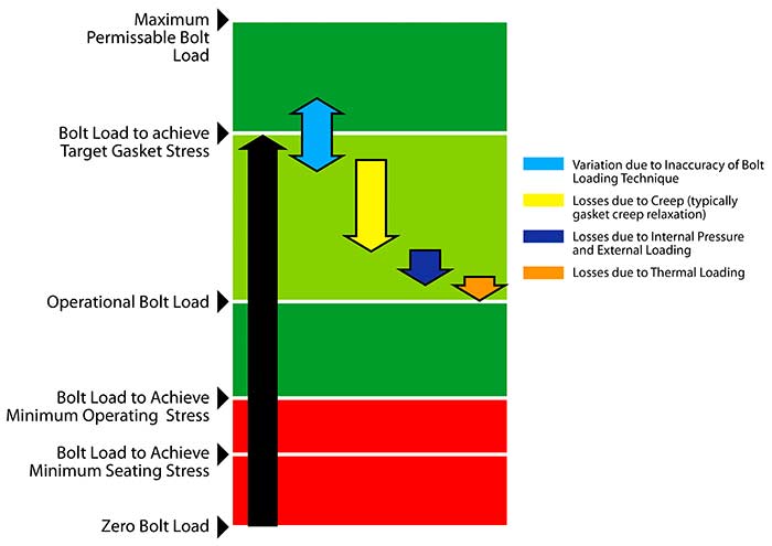 Image 2. Forces acting on a flange and gasket
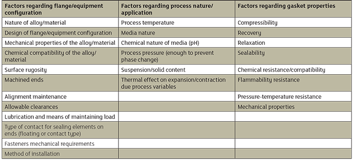 Table 1. Factors to consider in joint sealing
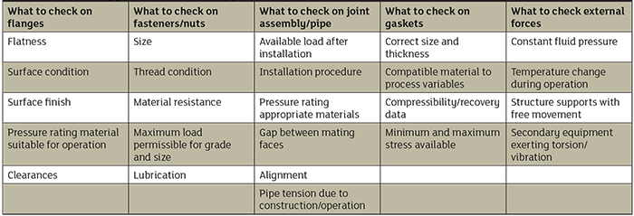 Table 2. Troubleshooting seal and gasket failure due to pipe strain